
Twinpass alarm remote
Finding the origin of the device
While looking for something completely different (a France Telecom pager) I stumbled upon some documentation for some sort of alarm system that was able to communicate with the said pager.
When browsing a bit of the documentation I noticed a specific device in the list shown in the user manual.
I recognized it and went to dig in the boxes filled with hardware waiting to be tested & hacked.
Here it is, the device I previously found is probably a remote for the DP8000 alarm system made by TwinPass
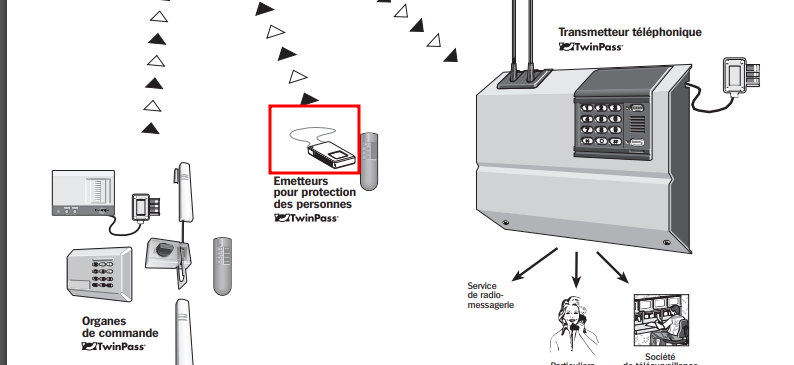
After a bit more research, it happens to be a device to remotely call emergecies, usually used by elderies in case of injuries. here is a more detailled documentation about this specific device

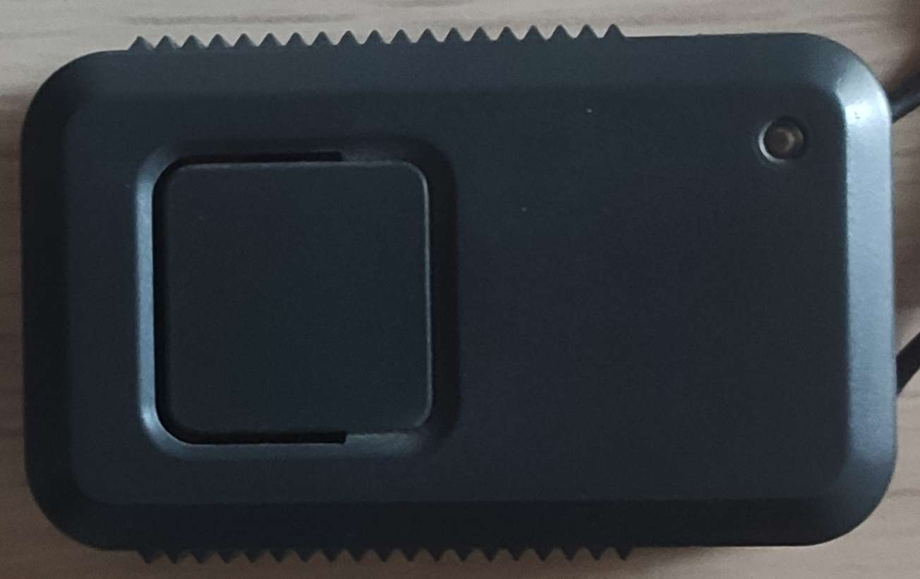
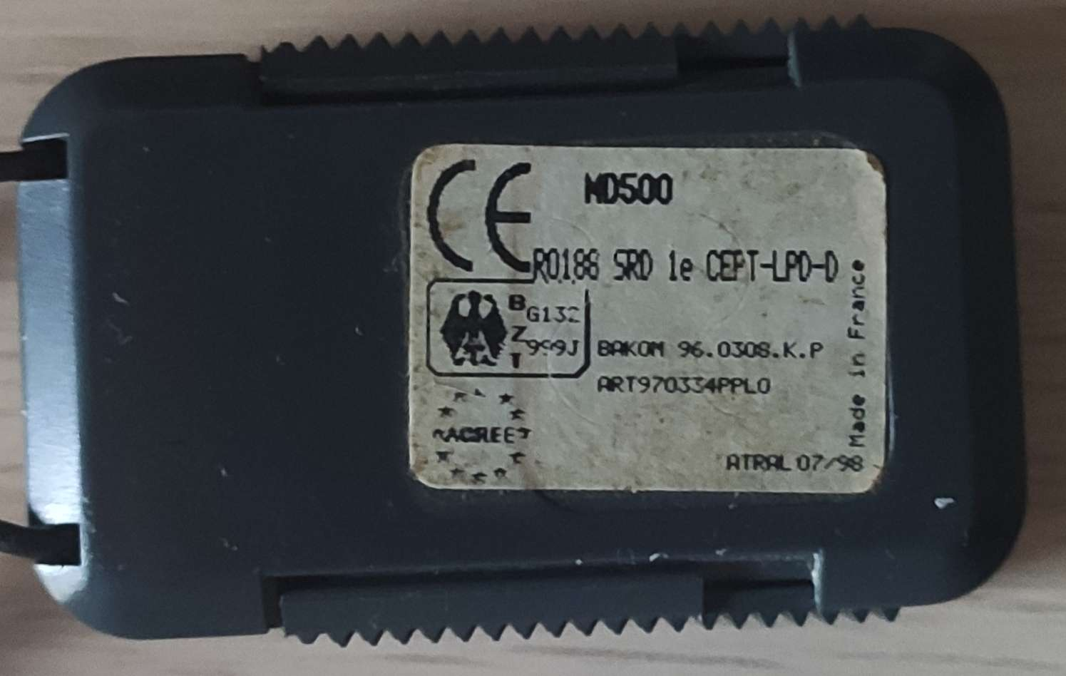
Pics of the device
Outer layer
Logic board
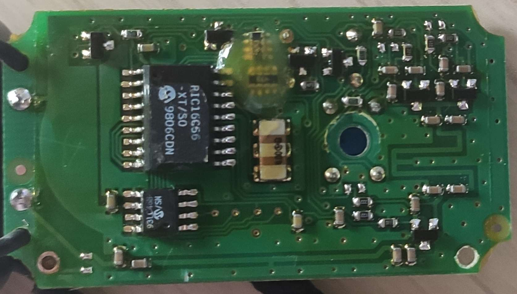
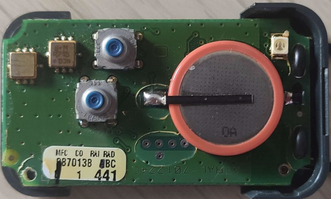
The two main components on the board are :
PIC16C56 EPROM/ROM-Based 8-bit CMOS Microcontroller Series
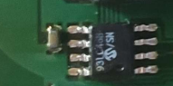
93LC46B EEPROM
But where is the antenna
If you take a look at the PCB, there are no antennas visible. I was confused at the beginning and then noticed the two soldering points on the left side of the first PCB photo. This is the link that is used to keep the device arount your neck, it’s mostly made of string, but the two ends are covered with thermoretractil tubing and soldered to the board, it means it’s made of metal, and my guess is that this is the antenna.
Read the EEPROM
On the backside of the PCB, it appears to be a 93LC46B EEPROM that is probably holding some interesting informations.
To get the data that is stored inside the chip, I’ll use a CH314A reader.
Before installing the prob to read the chip, I made a quick test with a multimeter just to be sure the chip wasn’t coated like a good chunk of the logic board. It revealed that all the logic board was under a fine layer of coating. I scratched the pins of the chip and then plugged the prob.
Hopefully it will work properly
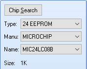
Once I started the software, I stumbled upon a problem : there are no options to dump such microchip device.
I tried with some other options to get a 1kb EEPROM but this wasn’t successful… I am not sure if the problem come from the fact that I don’t find the proper chip in the list or if I properly removed the coating… Even if I tried with some precision knives and a fill I can’t be sure the contacts are properly made since I can’t test the ground or other pins on other parts of the board as it’s certainly coated

Read the debug pins
Setting everything up
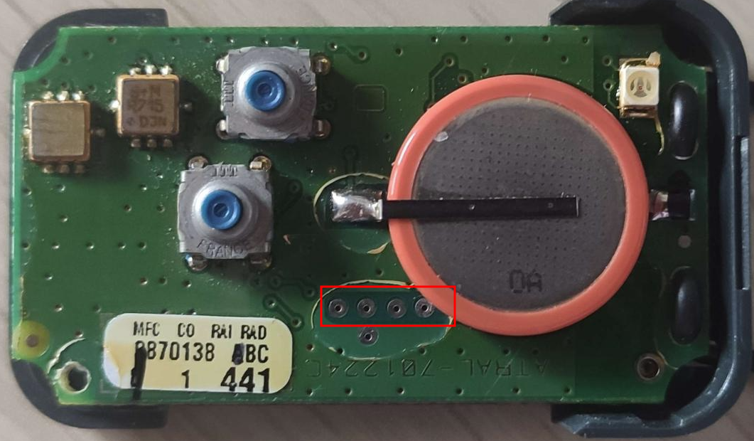
In the mean time, I decided to try to read the informations that could transit from what looks like to be test pins on the other side of the board.
These seems quite promising because there is no coating just on these pins as if they had a specific purpose on the device.
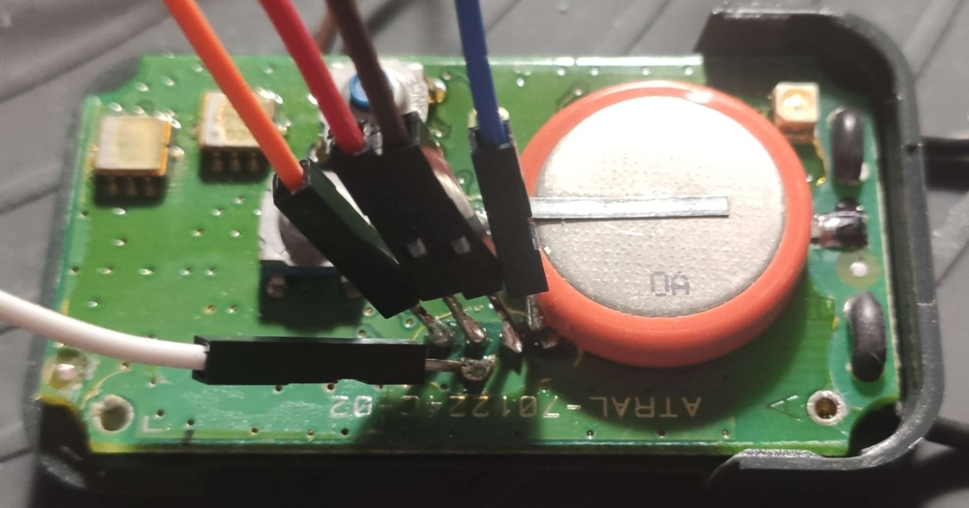
Now that I have some cables soldered to the board, I can easily connect the logic analyser to it.
As I don’t know where the ground is on the 5 pins, I decided to connect the ground of the logic analyser to the ground spot marked with a A. I removed some coating to make sure the contact will work fine, I tested it with a multimeter and everything seems OK
Once everything became a cabling mess, I started saleae logic 2 and plugged the logic analyser to the laptop. Then I started to record and pressed the button that is in the middle ( It seems to be the only one doing something as the other one doesn’t light up the LED but I’ll check that later on) in a short, then long way.
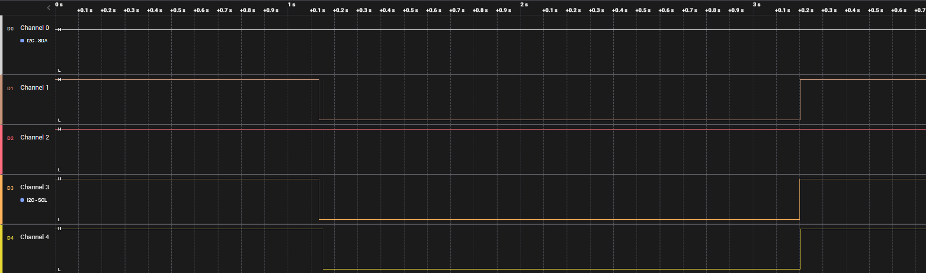
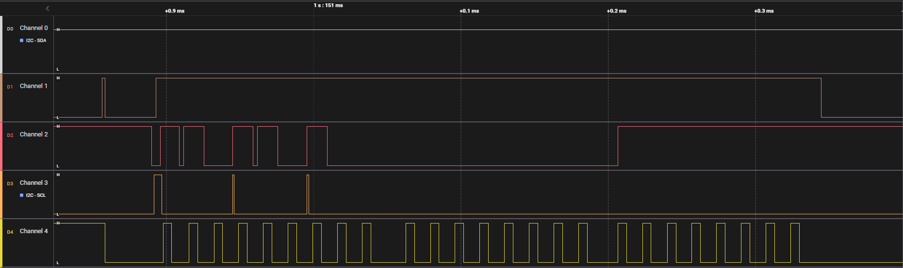
One press on the main button
When we press the button for a second, the led turns on red as long as we press.

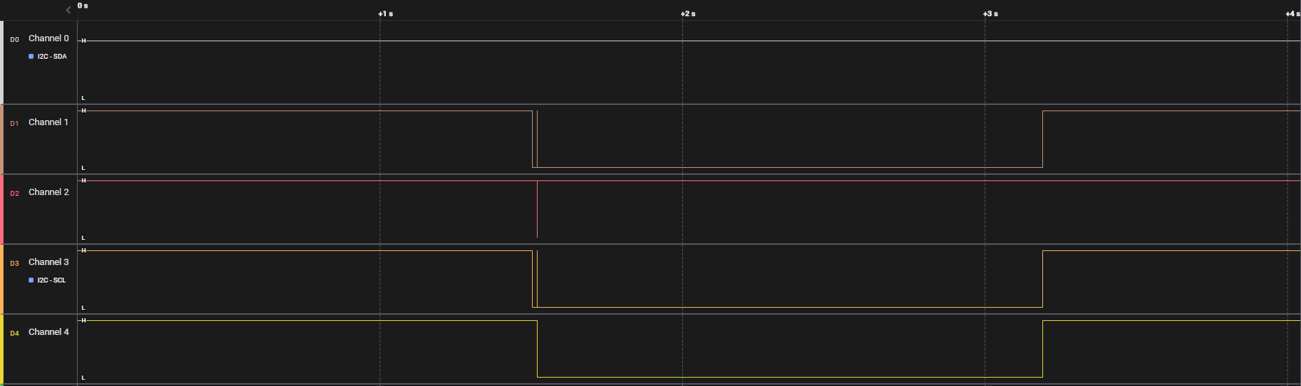
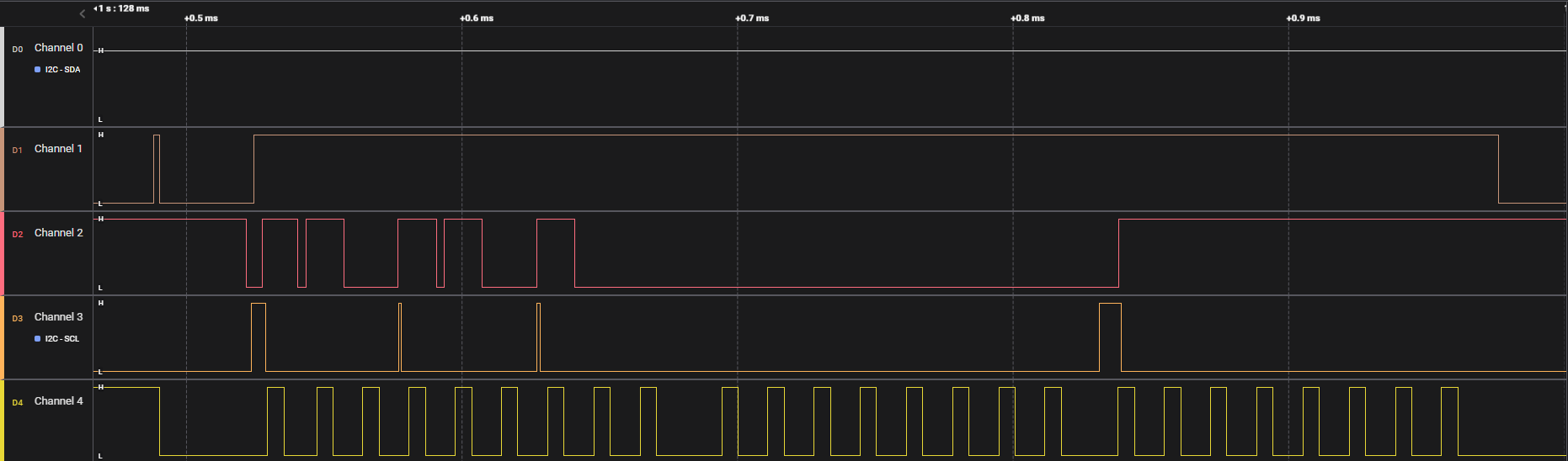
There is not much to see at first, the small bumps in the channels looks like misunderstood signal
However, when we zoom in, here is the result of those ‘misunderstood’ signals
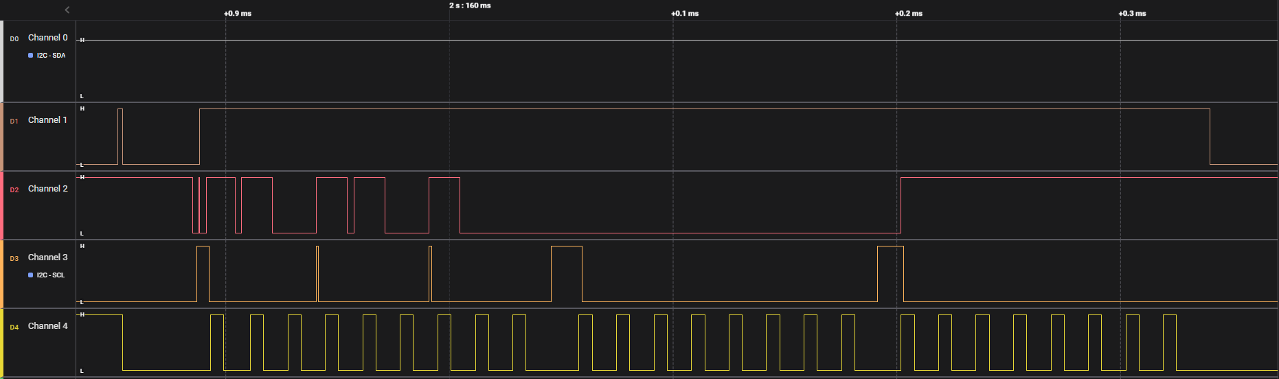
One long press on the main button
In the long press, the led will turn on red for the same time as regular press but then it will blink twice.
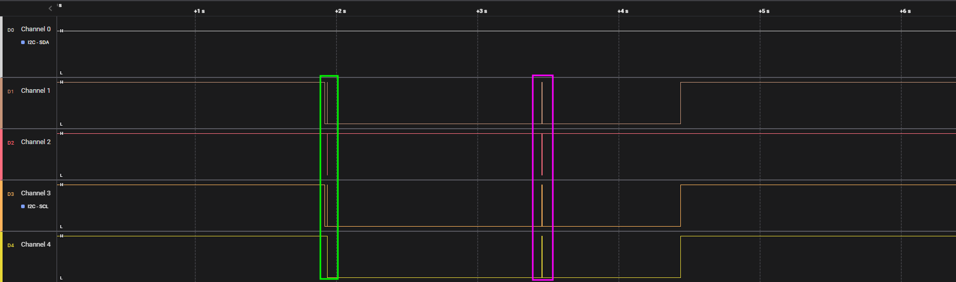
Here is the signal that has been captured
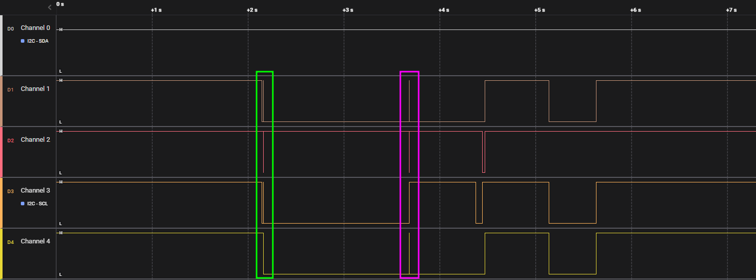

This time it looks like we have to areas with data a first one shown in green and a second one in purple
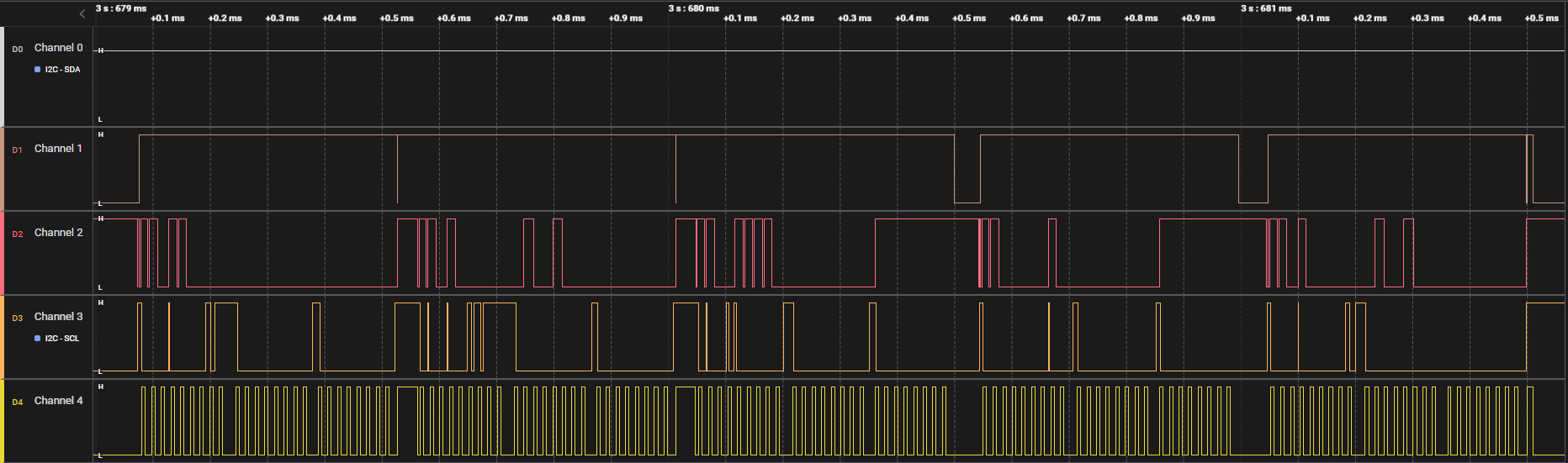
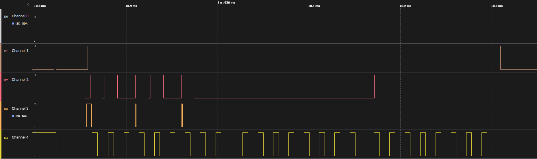
First data area
This data area seems to be the same as the one when we do a regular press, maybe some sort of igniter that is waiting for a longer press to send a real signal
We can see that there is a short pulse on the Channel 2 (red) at the start that is not in the regular press capture. This might be some capture error.
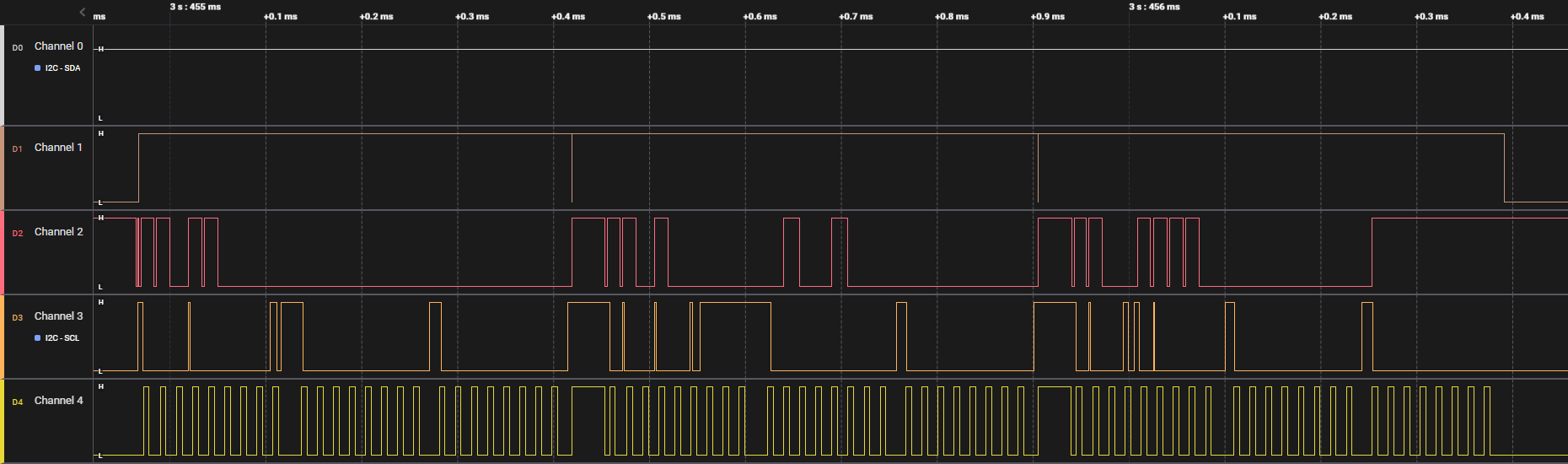
Second data area
The second data area seems to hold way more informations that the first one
Check the second button
On the board, there is a second button that isn’t usable on the device when not openned. I wonder if it send any sorts of signal. So I tried again to press it for a second and longer
One press on the button
This one seems very similar to the main button regular press

Yep, it definitly is the same data that is sent
One long press on the button
Once again, it looks like we have two areas with data one shown in green and the second in purple
Here is a detailled view of both areas
This time it looks like the informations that goes in the second area changed from the main button.
Decoding the data from the captured signal
The next step would be to decode the data that has been capture to get a better enderstanding of the informations that are sent by the remote.
Once such information is known, One thing that could be tried is to replicate the signal to emulate the remote, however, as I don’t own the entire alarm system, I would not be able to see if such operation work and the possible results and error that might occure.

Time to get back at it
After a while, I jumped back into the reverse of this device.
If managed to find the documentation of the remote itself and got some interesting informations.
The documentation can be found at this link