
Reversing Mac Donald’s table beacon - Part 1
Introduction
I managed to get my hands on a Mac Donald table beacon :


Let’s take a look at what’s inside
I decided to open it to see what’s inside, the active part of the beacon is at the top, locked in place with two screws.
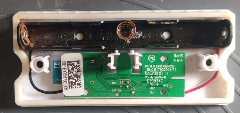
To be honest, there isn’t much things in the compartiment that hold the PCB, after removing the two 1.2V batteries here is the board we have :
 https://twitter.com/atc1441/status/1678707482452008960
Removing the battery holder to use bench PSU
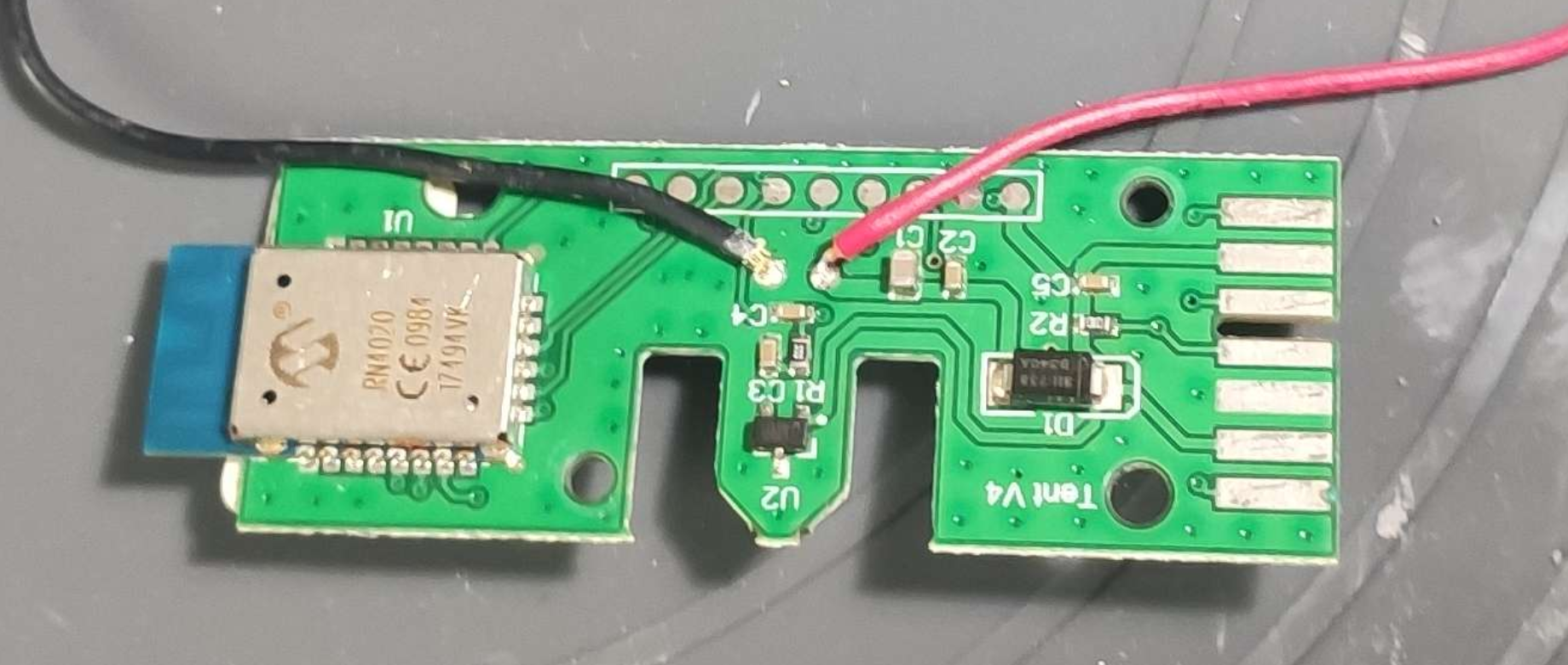
Seeing the state of the battery holder, I removed it to solder some jumper cable in order to power it with my bench power supply later in the tests
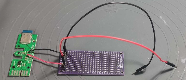
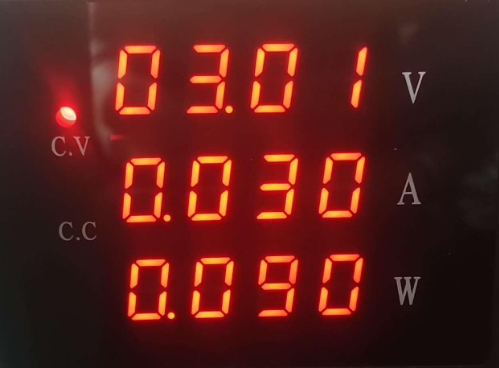
Now that we have a bench power supply linked to the board, we can try to power it up to make sure the board is still working by drawing some power
Probing the device
Let’s prob all the test points we can see on the PCB with a logic analyser, with a bit of luck, we could get some interesting informations from one of them
Finding the ground pins
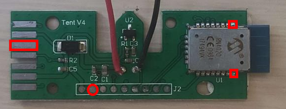
In order to properly use the logic analyser, we need to find the grounds to plug the analyser grounds to the board grounds.
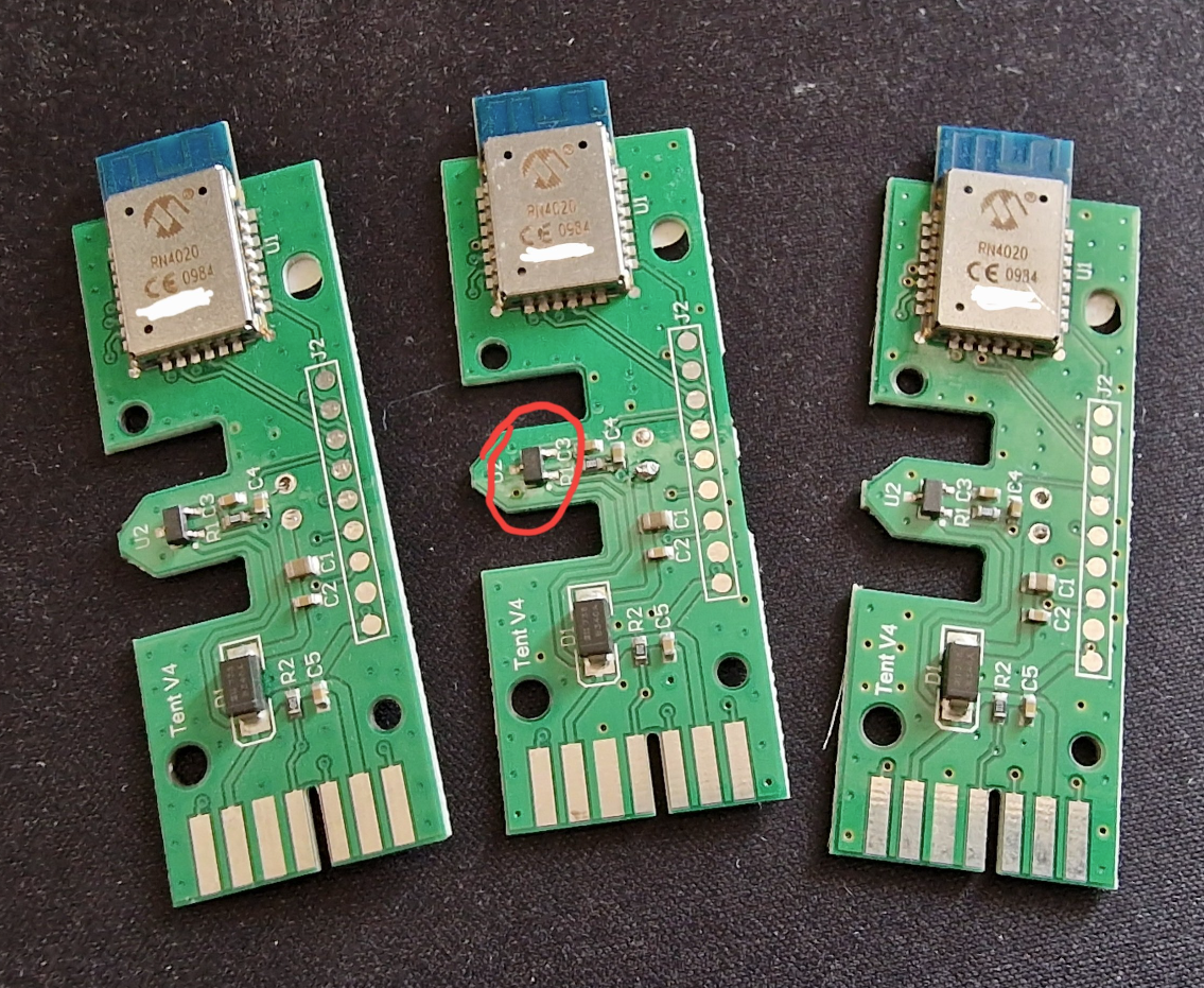
Using the multimeter we can find the following pins linked to the ground Marked in red in the photo

Probing all the pins
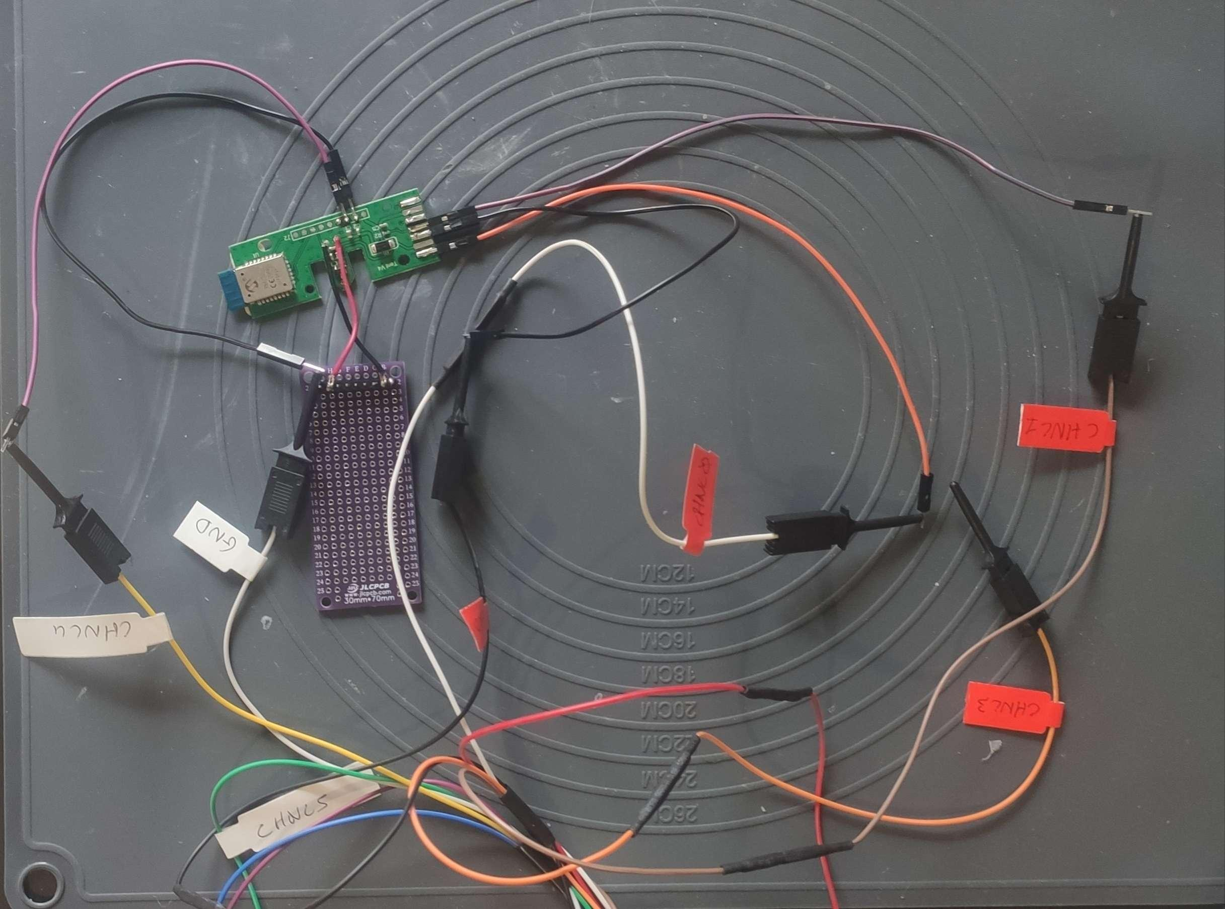
I finally decided to prob all the pins of the board to see who is talking to who.
Here is the result :

Yes, it takes some time to do these pics
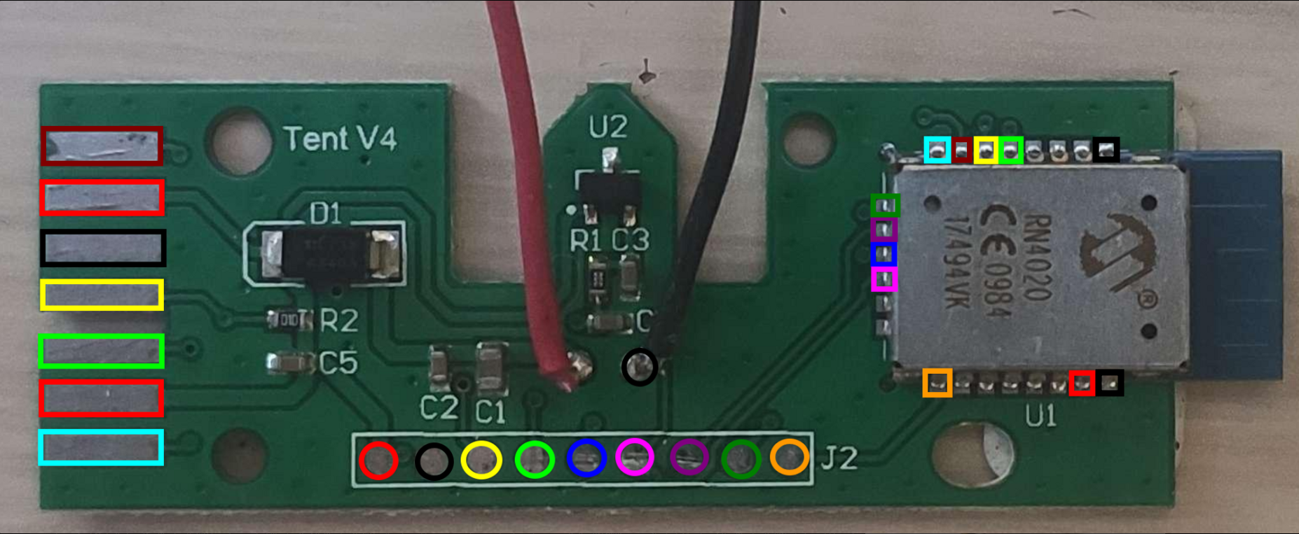
As we can see there is a lot of pins that goes to the wireless card, let’s take a look in depth on this chip
What is the wireless chip doin ?
Identifying the chip
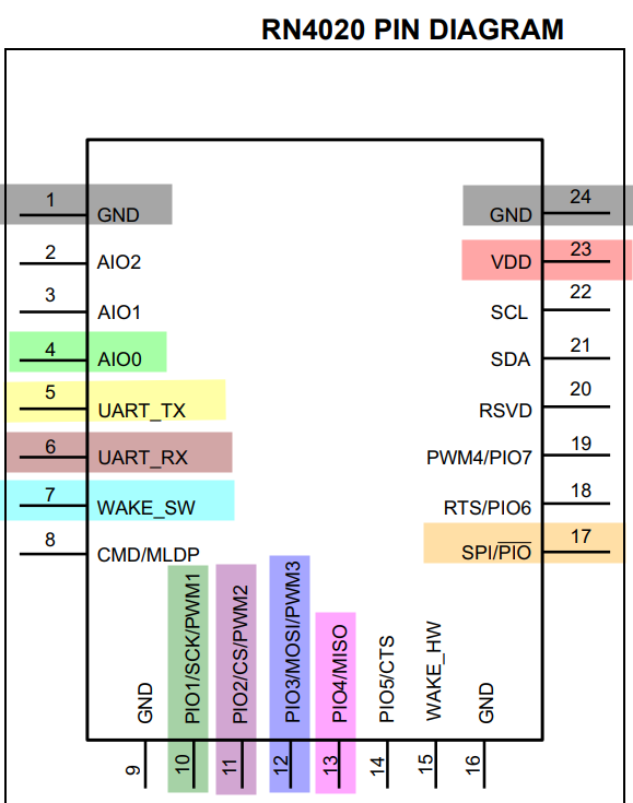
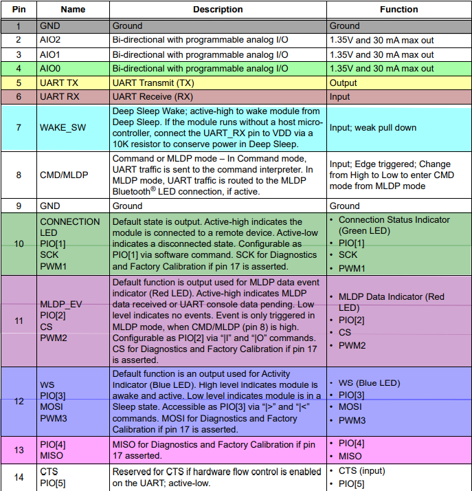
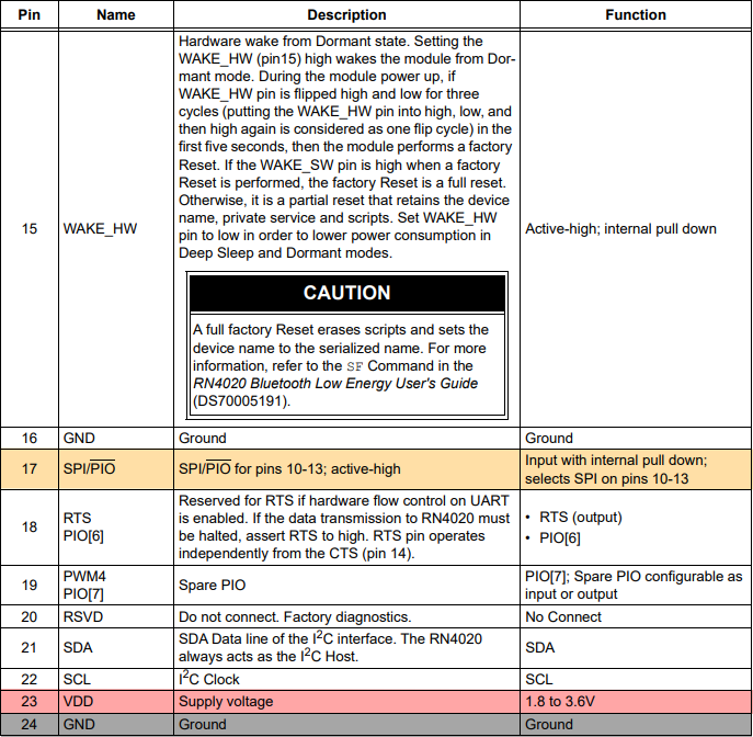
On the chip, there are some codes that help to identify the chip here RN4020
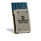
This page leads to the datasheet that hold more information that might be helpful later on

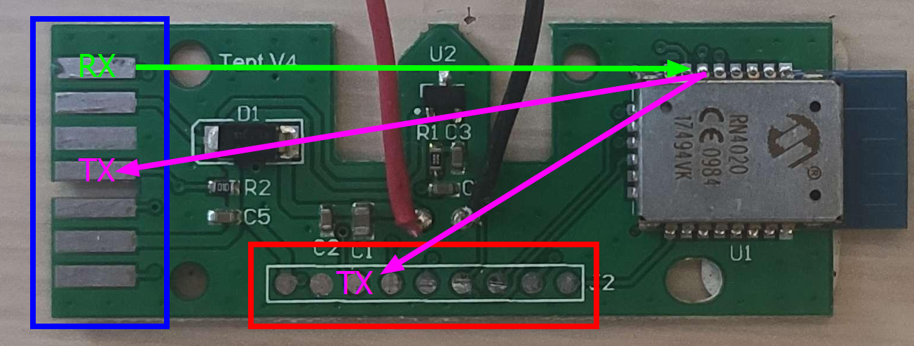
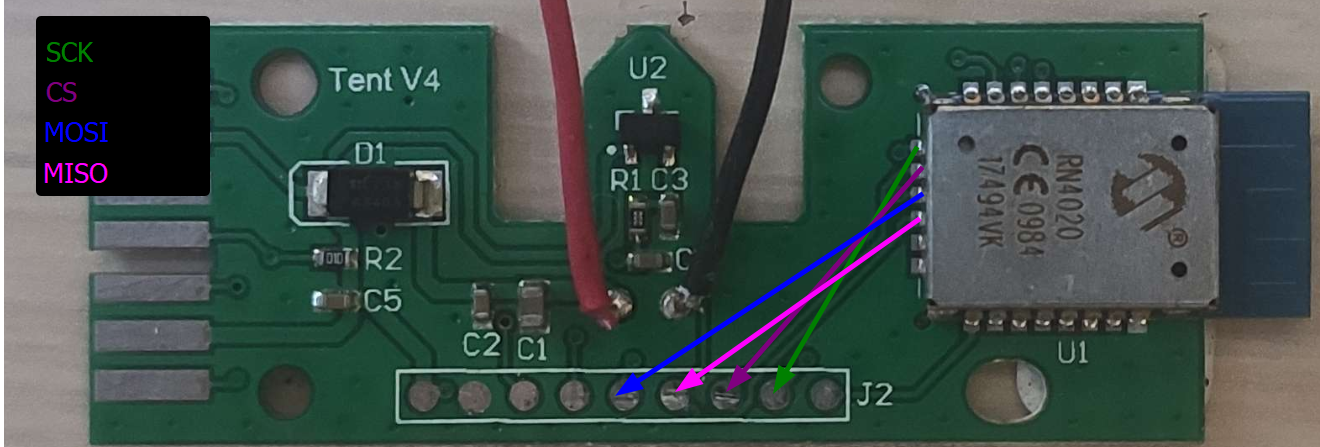
Identifying the pins used
The Blue one, that can read the information sent from the RN4020 and can also talk to it and the Red one, that can only listen to the information sent by the RN4020

Exploiting the UART port
Probing the chip
Now that we know we have some UART pins on the chip one of the things we could try to do is probing them to see what is going on.
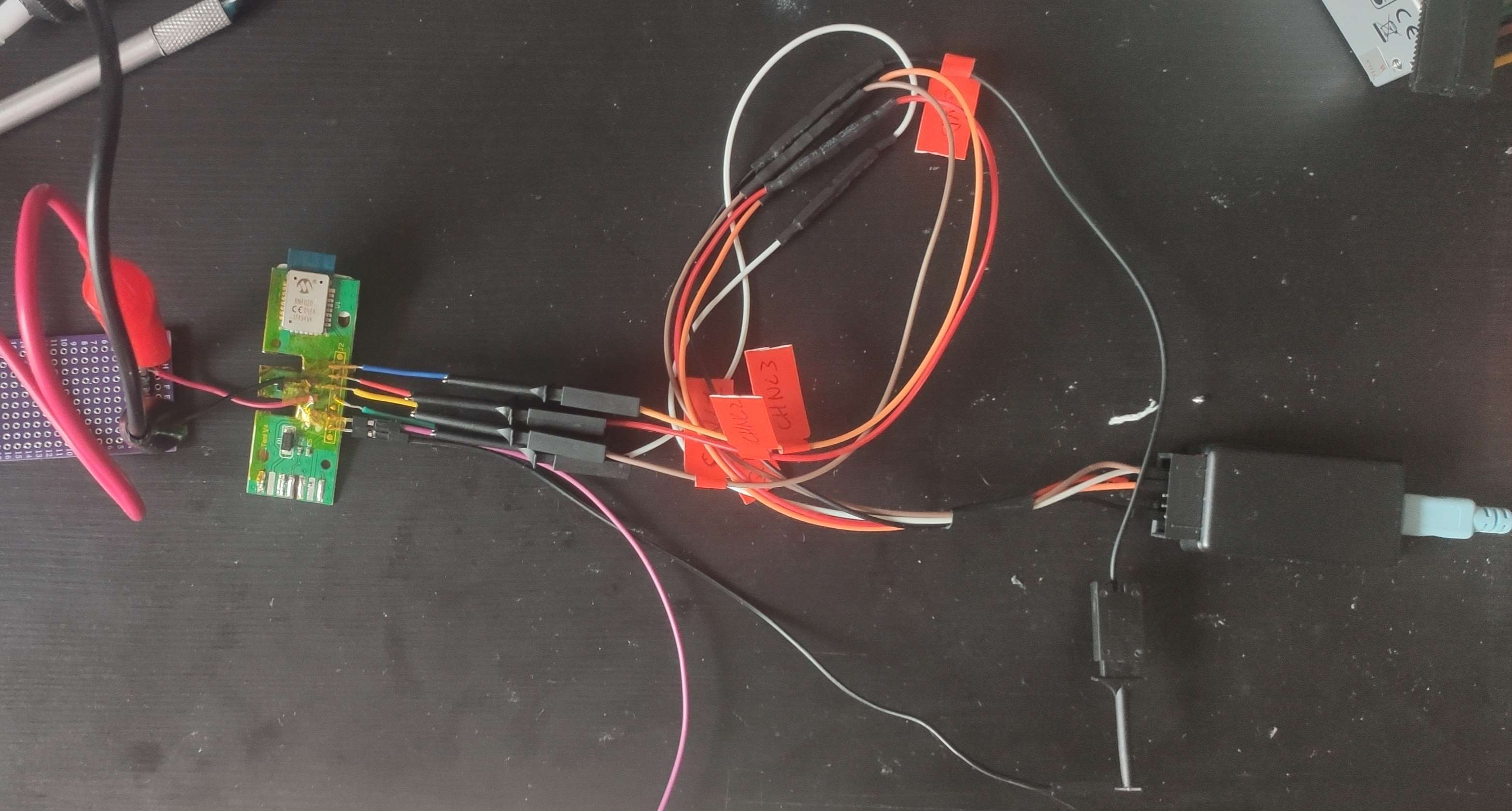
I decided to make the two “groups” probed independently to be able to test both. Here is a photo of the UART pins probed :
| Pin | Probe |
|---|---|
| GND | GND 1 |
| RX | Channel0 |
| TX | Channel 1 |
| Pin | Probe |
|---|---|
| GND | GND 2 |
| TX | Channel 4 |

Starting the logic analysis
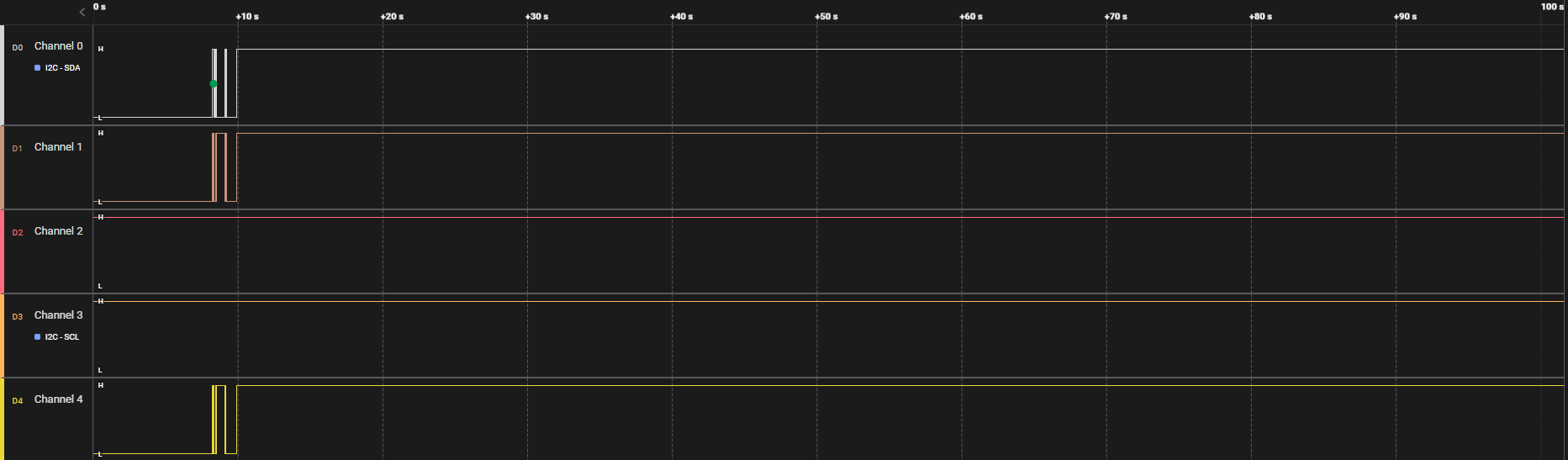
Took a look at the RX / TX pins of the logic board, but once the card is powered up, nothing seems to appear as shown in the following screenshot. the signal at start is just me messing with the bench power supply connectors
Exploiting the MISO / MOSI port
The other pins that could be tested would the the MISO / MOSI pins. To try them, it will require a bit more soldering job and probing
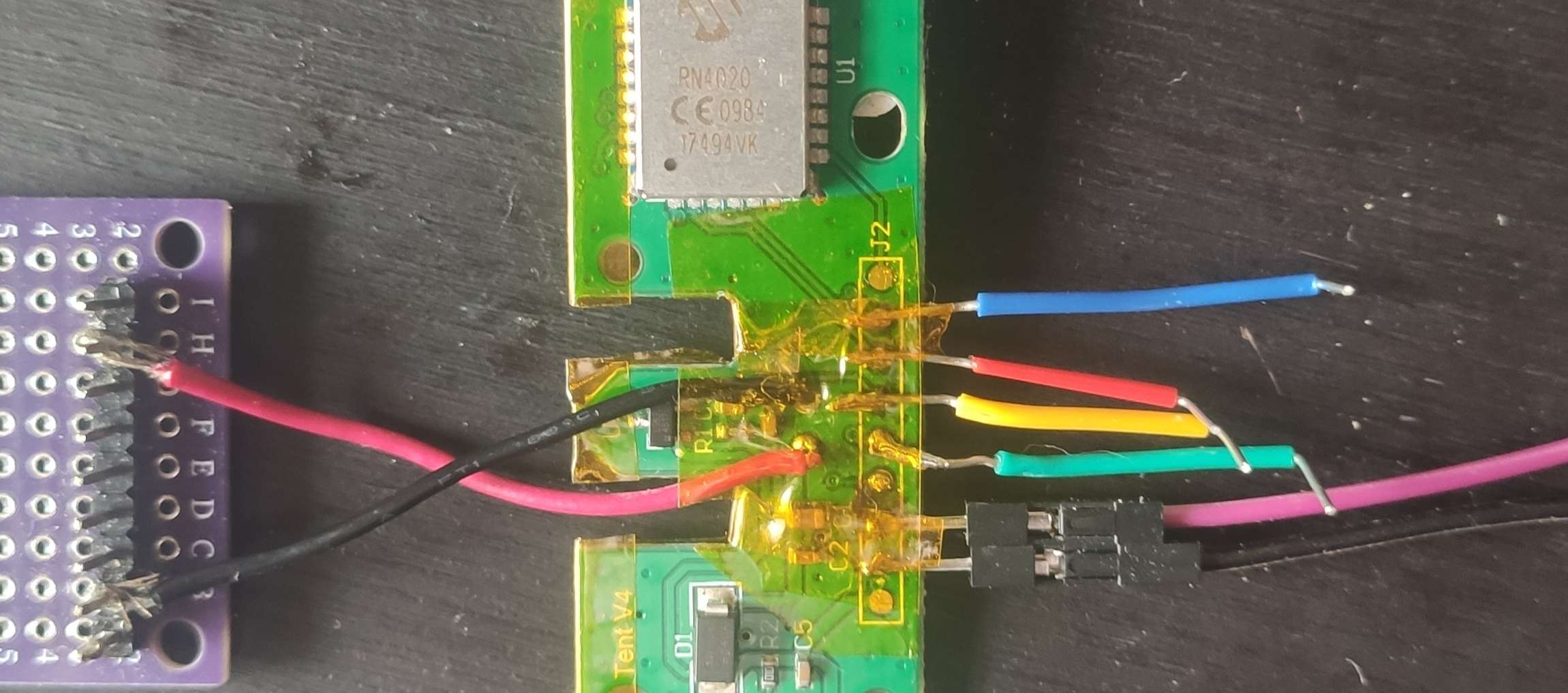
Time to hook on the logic analyser and boot up logic 2.4.7 to see if those pins are more chatty

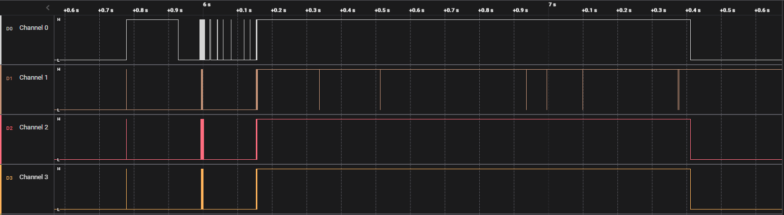

It looks like there are some informations going through these pins, but even with a closer inspection and the tools that logic 2 offers I haven’t been able to determine the content of the communication.
My logic analyser seems to produce a lot of noise on this device for some reason
Listening for the Bluetooth chip
Nonetheless there is a Bluetooth chip on the logic board and this chip must be talking, I decided to take a closer look at (maybe a bit late but whatsoever) with the smartphone app called LightBlue

Here are the information I can get from it
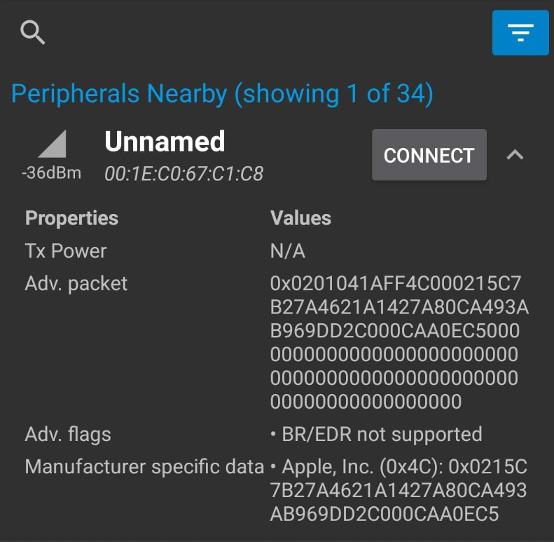
sadly no more infos are available since it is not possible to connect to the Bluetooth device


Conclusion
I then talked to some friends from Switzerland that worked there, it appears that there are several dozen of antennas in the restaurant and they do some sort of triangulation to know where the beacons based on their MAC address broadcast. These antennas talk to a defined computer, a database would do the link between the MAC addresses and the number on the beacon used by the user. From there this computer would display the table on which it is to the employee working there.
I wanted to give it a try and simulate a beacon using my Flipper zero to get the beacon at two tables simultaneously. However, it looks like the MacDonald near my place does not use these types of beacon…