
NE555N
Présentation
This small chip is used to generate a clock that can goes up to 2 MHz
Pin layout :
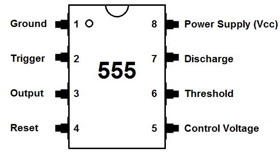
| Pin Number | Pin Name | Pin Function | Pin Number | Pin Name | Pin Function |
|---|---|---|---|---|---|
| 1 | Ground | Pin 1 connects the 555 timer chip to ground. | 5 | Control Voltage | Pin 5 is the control pin. In most 555 timer circuits, this pin is simply connected to ground, usually through a small capacitor, about 0.01 µF capacitor. This capacitor serves to level out any fluctuations in the power supply voltage that might affect the operation of the timer.Some circuits (though rare) do use a resistor between the control pin and Vcc to apply a small voltage to pin 5. This voltage alters the threshold voltage, which in turn changes the timing interval. Most circuits do not use this capability, though. |
| 2 | Trigger | Pin 2 is the trigger pin. It works like a starter pistol to start the 555 timer running. The trigger is an active low trigger, which means that the timer starts when voltage on pin 2 drops to below 1/3 of the supply voltage. When the 555 is triggered via pin 2, the output on pin 3 goes high. | 6 | Threshold | Pin 6 is the threshold pin. The purpose of this pin is to monitor the voltage across the capacitor that's discharged by pin 7. When this voltage reaches 2/3 of the supply voltage (Vcc), the timing cycle ends, and the output on pin 3 goes low. |
| 3 | Output | Pin 3 is the output pin. 555 timer's output is digital in nature. It is either high or low. The output is either low, which is very close to 0V, or high, which is close to the supply voltage that's placed on pin 8.The output pin is where you would connect the load that you want the 555 timer to power. This may be an LED, in the case of a 555 timer LED flasher circuit. | 7 | Discharge | Pin 7 is the discharge pin. This pin is used to discharge an external capacitor that works in conjunction with a resistor to control the timing interval. In most circuits, pin 7 is connected to the supply voltage through a resistor and to ground through a capacitor. |
| 4 | Reset | Pin 4 is the reset pin. This pin can be used to restart the 555 timer's timing operation.This is an active low input, just like the trigger input. Thus, pin 4 must be connected to the supply voltage of the 555 timer to operate. If it is momentarily grounded, the 555 timer's operation is interrupted and won't start again until it's triggered again via pin 2. | 8 | Power Supply (Vcc) | Pin 8 is connected to the positive power supply voltage.555 timer ICs need DC voltage in order to operate. This is the pin which connects to the DC voltage to power the 555 chip.The voltage must be at least 4.5V and no greater than 15V. It's common to run 555 timer circuits using 4 AA or AAA batteries for 6V or a single 9V battery. |
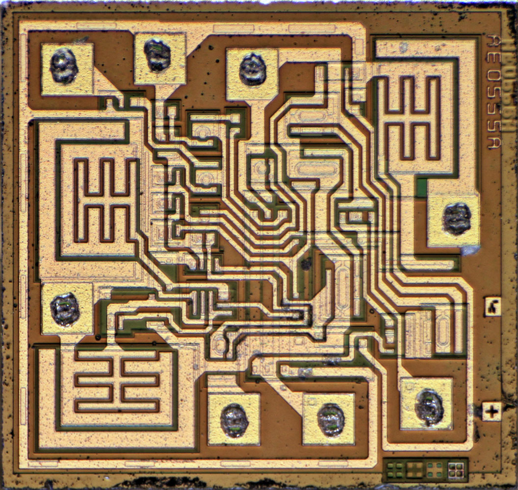
Tests of the chip
Sources
555 Astable Circuit Calculator
The 555 timer is capable of being used in astable and monostable circuits. In an astable circuit, the output voltage alternates between VCC and 0 volts on a continual basis. By selecting values for R1, R2 and C we can determine the period/frequency and the duty cycle.