MJSXJ09CM - Recovering Firmware and Backdooring
First glance at the device
I decided to disassemble the device and take a closer look at the hardware.
Let’s talk with the board
Taking pictures of the device as been useful in identifying a serial port on the board. Although there is no label around the pins, I identified the UART pins with the help of a multimeter. I wired the board to simplify the probing of the device.
Probing layout
Here is the list of the pins :
- red[RX]
- green[TX]
- black[GND]
Connect with USB over UART
Now that we have the UART connection to the board, we can try to connect the device to a computer using a

I was expecting to end up on a shell output showing me the logs of the boot process and eventually some information regarding the configuration or the OS that was in the device.
However, once we connect to the UART, something unexpected happened.

Time for some debug
Reset the device with Mi Home application

The device came from a lab and had been already tested multiple times, this mean that it might have some configuration fault and so on.
Since I miss most of the device, I don’t know if I can completely performe the installation… But let’s give it a try anyways.
I created a WiFi network for this device, opened the Xiaomi “mi home” application and tried to perform on adding the device to my fake den
(yeah, we try broken and unknown IoT stuff but I’ve build a fake den for them, mine wont get infected by all this)
Well, the camera is on the network, and the reset seems to have kinda worked, the issue now is that the camera should be displaying me some 4 digit pin code to enter on the application to finish the setup. I can’t get this code since I don’t have any components linked to a display or anything.
Reset the device and see what the UART tells us
The second idea I had was to read the output of the UART when proceeding to a factory reset, maybe we could get some more informations like a default auth code, a wifi network to access the device or anything that could unstuck the situation
Here is the complete output of the UART link :
Stopping netcheck...Start detecting tf_update.img mount sdcard agagin
mount: mounting /dev/mmcblk0p1 on /mnt/sdcard failed: Device or resource busy
mount: mounting /dev/mmcblk0 on /mnt/sdcard failed: Device or resource busy
do nothing
Stopping crond...init
do nothing
No connection! Set fake rssi= -80!!!
Stopping wifi...killall: wpa_supplicant: no process killed
Deauthenticate all stations!
80211> CFG80211_OpsStopAp ==>
killall: dhcpd: no process killed
================> DOWN : RTMP_SEM_EVENT_WAIT(STA)
[_MI_AI_IMPL_FreeTmpBuffer:3614] free tmp buffer.
unlink cmd rsp urb
<<<MI_SYS_IMPL_UnBindChnPort[4103] InputPort(12 0 2 0), OutputPort(7 0 0 2) , ret = a0092003
<=============== DOWN : RTMP_SEM_EVENT_UP(STA)
Stopping networkUnkown frame_type = b0, req = 0
: OK
imi stop hw wat ok
[MI WRN ]: MI_VPE_IMPL_DisablePort[7810]: the port has not been enabled

[MI WRN ]: MI_VENC_IMPL_StopRecvPic[9232]: CH 0 is not created.
<<<MI_SYS_IMPL_UnBindChnPort[4103] InputPort(12 0 2 0), OutputPort(7 0 0 2) , ret = a0092003

<<<MI_RGN_IMPL_DetachFromChn[1680] pstChnPort and handle not matched.
<<<MI_RGN_IMPL_DetachFromChn[1680] pstChnPort and handle not matched.

<<<MI_SYS_IMPL_UnBindChnPort[4103] InputPort(12 0 1 0), OutputPort(7 0 0 2) , ret = a0092003
[MI WRN ]: MI_VPE_IMPL_DisablePort[7810]: the port has not been enabled

[HALSCL]_HalSclDestoryRealTimeModeOrLastChannel Destroy process fence d9

===== MhalCameraClose begin, ch = 0, VifMask: 0x3 =====
===== MhalCameraClose, 10773 end. =====
[MI WRN ]: _MI_VPE_ModuleonGetInterBindOutputPortPassId[4744]: MODEID 7, not for vpe 7
[MI WRN ]: _MI_VPE_ModuleonGetInterBindOutputPortPassId[4745]: chn 0, not create

[MI WRN ]: _MI_SYS_IMPL_GetOutputPortInfo[2827]: not found [eModId 4,u32DevId 0, chnID=0, outputPortId=0]
client [611] disconnected, module:ao
client [611] disconnected, module:ai
client [611] disconnected, module:shadow
MI_SHADOW_IMPL_DeInit 1829
client [611] disconnected, module:divp
[DIP] Virtual IRQ: 36
[CMDQ]Release CMDQ(2) service
client [611] disconnected, module:venc
[CMDQ]Release CMDQ(3) service
client [611] disconnected, module:rgn
cat: read error:watchdog: watchdog0: watchdog did not stop!
 Invalid argument
perpctl fatal: perpd not running on control socket /etc/perp/.control/perpd.sock: connection refused (ECONNREFUSED)
Region Buffer Clear ready!!!!
client [611] disconnected, module:vpe
[CMDQ]Release CMDQ(0) service
CmdqProcDeInit 722
ReleaseAllBuffer count =0
[CMDQ]Release CMDQ(1) service
client [611] disconnected, module:vif
client [611] disconnected, module:sensor
client [611] disconnected, module:sys
rmmod: can't unload module 'drv_ms_cus_sc3235_MIPI': No such file or directory
srcfg driver 1.0 exit success
rmmod: can't unload module 'exfat': No such file or directory
usbcore: deregistering interface driver usb-storage
Sstar-ehci-1 soc:Sstar-ehci-1: remove, state 1
usb usb1: USB disconnect, device number 1
usb 1-1: USB disconnect, device number 2
STA : rtusb_disconnect: unregister usbnet usb-mstar-1
================> DOWN : RTMP_SEM_EVENT_WAIT(STA)
<=============== DOWN : RTMP_SEM_EVENT_UP(STA)
RtmpOSNetDevDetach(): RtmpOSNetDeviceDetach(), dev->name=wlan0!
vfree net device ops <- c3754000
80211> unregister/free wireless device
 STA : RTUSB disconnect successfully
root hub reinitial [usbdis]
Sstar-ehci-1 soc:Sstar-ehci-1: USB bus 1 deregistered
---> @@@@@@ STA : rtusb exit
usbcore: deregistering interface driver rt2870
<--- STA : rtusb exit
remove prealloc ok
usbcore: deregistering device driver usb
usbcore: deregistering interface driver usbfs
usbcore: deregistering interface driver hub
mmc0: card 0001 removed
[Padmux]reset PAD54(reg 0x101e00:8; mask0xc) t0 GPIO (org: SD_MODE)
mstar notify driver remove successfully
RPC: Unregistered named UNIX socket transport module.
RPC: Unregistered udp transport module.
RPC: Unregistered tcp transport module.
RPC: Unregistered tcp NFSv4.1 backchannel transport module.
Stopping logging: OK
S00init stop do nothing
umount: /dev/mmcblk0p1 busy - remounted read-only
umount: devtmpfs busy - remounted read-only
The system is going down NOW!
Sent SIGTERM to all processes
Sent SIGKILL to all processes
Requesting system reboot
reboot: Restarting system
1
IPL g05c44be
D-05
SPI 54M
64MB
BIST0_0001-OK
[SPI_NOR]
MXP found at 0x00020000
offset:00010000
Checksum OK

IPL_CUST g05c44be
runUBOOT()
[SPI_NOR]
MXP found at 0x00020000
offset:00030000
 -Decompress BDMA XZ
 -Decompress BDMA XZ
XZ decomp_size=0x0004a8e8
 pvLoadAddr:23d00000
 pvRunAddr:23e00000
 -Verify CRC32 passed!
  decomp_size=0x00000000
Disable MMU and D-cache before jump to UBOOT▒

U-Boot 2015.01 (May 17 2021 - 15:28:25), Build: jenkins-ipc029a02_new_key-283

Version: I6g2b9a2f0
I2C:   ready
DRAM:
gpio debug MHal_GPIO_Pad_Set:603
gpio[14] is 0
gpio debug MHal_GPIO_Pad_Set:603
gpio[14] is 1
WARNING: Caches not enabled
MMC:   MStar SD/MMC: 0
nor_flash_mxp allocated success!!
Flash is detected (0x090F, 0x1C, 0x70, 0x18)
SF: Detected nor0 with total size 16 MiB
MXP found at mxp_offset[3]=0x00020000, size=0x1000
env_offset=0x4F000 env_size=0x1000
Flash is detected (0x090F, 0x1C, 0x70, 0x18)
SF: Detected nor0 with total size 16 MiB
In:    serial
Out:   serial
Err:   serial
Net:   Net Initialization Skipped
No ethernet found.
read file start
reading tf_update.img
** Unable to read file tf_update.img **
read len = -1, actlen = 0
read file tf_update.img error.
Flash is detected (0x090F, 0x1C, 0x70, 0x18)
SF: Detected nor0 with total size 16 MiB
SF: 2097152 bytes @ 0x50000 Read: OK
##  Booting kernel from Legacy Image at 22000000 ...
   Image Name:   MVX4##I6B0g2b9a2f0KL_LX409##[BR:
   Image Type:   ARM Linux Kernel Image (lzma compressed)
   Data Size:    1510792 Bytes = 1.4 MiB
   Load Address: 20008000
   Entry Point:  20008000
   Verifying Checksum ... OK
   Uncompressing Kernel Image ...
[XZ] !!!reserved 0x21000000 length=0x 1000000 for xz!!
   XZ: uncompressed size=0x312000, ret=7
OK
atags:0x20000000

Starting kernel ...

Booting Linux on physical CPU 0x0
Linux version 4.9.84 (ubuntu@eac7de836e2a) (gcc version 4.9.4 (Buildroot 2017.08-gc7bbae9-dirty) ) #1 PREEMPT Mon May 17 15:29:55 CST 2021
CPU: ARMv7 Processor [410fc075] revision 5 (ARMv7), cr=50c53c7d
CPU: div instructions available: patching division code
CPU: PIPT / VIPT nonaliasing data cache, VIPT aliasing instruction cache
early_atags_to_fdt() success
OF: fdt:Machine model: INFINITY6B0 SSC009A-S01A QFN88
[ERR] LX_MEM, LX_MEM2, LX_MEM3 not 1MB aligned
LXmem is 0x3fe0000 PHYS_OFFSET is 0x20000000
Add mem start 0x20000000 size 0x3fe0000!!!!

LX_MEM  = 0x20000000, 0x3fe0000
LX_MEM2 = 0x0, 0x0
LX_MEM3 = 0x0, 0x0
EMAC_LEN= 0x0
DRAM_LEN= 0x0
deal_with_reserve_mma_heap memblock_reserve success mma_config[0].reserved_start=
0x22be0000

cma: Reserved 2 MiB at 0x22800000
Memory policy: Data cache writeback
CPU: All CPU(s) started in SVC mode.
Built 1 zonelists in Zone order, mobility grouping on.  Total pages: 11144
Kernel command line: console=ttyS0,115200 root=/dev/mtdblock2 rootfstype=squashfs ro init=/linuxrc LX_MEM=0x3fe0000 mma_heap=mma_heap_name0,miu=0,sz=0x1400000 mma_memblock_remove=1
PID hash table entries: 256 (order: -2, 1024 bytes)
Dentry cache hash table entries: 8192 (order: 3, 32768 bytes)
Inode-cache hash table entries: 4096 (order: 2, 16384 bytes)
Memory: 38984K/44928K available (1779K kernel code, 200K rwdata, 948K rodata, 96K init, 133K bss, 3896K reserved, 2048K cma-reserved)
Virtual kernel memory layout:
    vector  : 0xffff0000 - 0xffff1000   (   4 kB)
    fixmap  : 0xffc00000 - 0xfff00000   (3072 kB)
    vmalloc : 0xc3000000 - 0xff800000   ( 968 MB)
    lowmem  : 0xc0000000 - 0xc2be0000   (  43 MB)
    modules : 0xbf800000 - 0xc0000000   (   8 MB)
      .text : 0xc0008000 - 0xc01c5158   (1781 kB)
      .init : 0xc02ce000 - 0xc02e6000   (  96 kB)
      .data : 0xc02e6000 - 0xc0318058   ( 201 kB)
       .bss : 0xc031a000 - 0xc033b4b4   ( 134 kB)
SLUB: HWalign=64, Order=0-3, MinObjects=0, CPUs=1, Nodes=1
Preemptible hierarchical RCU implementation.
        Build-time adjustment of leaf fanout to 32.
NR_IRQS:16 nr_irqs:16 16
ms_init_main_intc: np->name=ms_main_intc, parent=gic
ms_init_pm_intc: np->name=ms_pm_intc, parent=ms_main_intc
ss_init_gpi_intc: np->name=ms_gpi_intc, parent=ms_main_intc
Find CLK_cpupll_clk, hook ms_cpuclk_ops
arm_arch_timer: Architected cp15 timer(s) running at 6.00MHz (virt).
clocksource: arch_sys_counter: mask: 0xffffffffffffff max_cycles: 0x1623fa770, max_idle_ns: 440795202238 ns
sched_clock: 56 bits at 6MHz, resolution 166ns, wraps every 4398046511055ns
Switching to timer-based delay loop, resolution 166ns
console [ttyS0] enabled
Calibrating delay loop (skipped), value calculated using timer frequency.. 12.00 BogoMIPS (lpj=60000)
pid_max: default: 4096 minimum: 301
Mount-cache hash table entries: 1024 (order: 0, 4096 bytes)
Mountpoint-cache hash table entries: 1024 (order: 0, 4096 bytes)
CPU: Testing write buffer coherency: ok
Setting up static identity map for 0x200081c0 - 0x200081f0
devtmpfs: initialized
VFP support v0.3: implementor 41 architecture 2 part 30 variant 7 rev 5
clocksource: jiffies: mask: 0xffffffff max_cycles: 0xffffffff, max_idle_ns: 19112604462750000 ns
futex hash table entries: 16 (order: -4, 448 bytes)
NET: Registered protocol family 16
DMA: preallocated 256 KiB pool for atomic coherent allocations


Version : MVX4##I6B0g2b9a2f0KL_LX409##[BR:HEAD]#XVM

GPIO: probe end[ss_gpi_intc_domain_alloc] hw:42 -> v:49
[MS_PM_INTC] hw:20 -> v:52
hw-breakpoint: found 5 (+1 reserved) breakpoint and 4 watchpoint registers.
hw-breakpoint: maximum watchpoint size is 8 bytes.
clocksource: Switched to clocksource arch_sys_counter
NET: Registered protocol family 2
TCP established hash table entries: 1024 (order: 0, 4096 bytes)
TCP bind hash table entries: 1024 (order: 2, 20480 bytes)
TCP: Hash tables configured (established 1024 bind 1024)
UDP hash table entries: 128 (order: 0, 6144 bytes)
UDP-Lite hash table entries: 128 (order: 0, 6144 bytes)
NET: Registered protocol family 1
hw perfevents: enabled with armv7_cortex_a7 PMU driver, 5 counters available
workingset: timestamp_bits=30 max_order=14 bucket_order=0
squashfs: version 4.0 (2009/01/31) Phillip Lougher
jffs2: version 2.2. © 2001-2006 Red Hat, Inc.
io scheduler noop registered
io scheduler deadline registered (default)
libphy: Fixed MDIO Bus: probed
i2c /dev entries driver
1f221000.uart0: ttyS0 at MMIO 0x0 (irq = 37, base_baud = 10800000) is a unknown
1f221200.uart1: ttyS1 at MMIO 0x0 (irq = 38, base_baud = 10800000) is a unknown
1f220400.uart2: ttyS2 at MMIO 0x0 (irq = 40, base_baud = 10800000) is a unknown
[gpioi2c] sda-gpio=8, scl-gpio=9
MSYS: DMEM request: [BDMA_FSP_WBUFF]:0x00010040
MSYS: DMEM request: [BDMA_FSP_WBUFF]:0x00010040 success, CPU phy:@0x22850000, virt:@0xC2850000
[Ser flash] phys=0x22850000, virt=0xc2850000, bus=0x02850000 len:0x10040
[FSP] Unknown flash type (0xFF, 0xFF, 0xFF) and use default flash type 0x0000
[FSP] 1-1-1 FAST_READ MODE
mtd .name = NOR_FLASH, .size = 0x01000000 (16MiB)
 .erasesize = 0x00010000 .numeraseregions = 0
MXP_PARTS!!
MXP found at mxp_offset[3]=0x00020000, size=0x1000
Creating 6 MTD partitions on "NOR_FLASH":
0x000000000000-0x000000050000 : "BOOT"
0x000000050000-0x000000250000 : "KERNEL"
0x000000250000-0x0000009b0000 : "ROOTFS"
0x0000009b0000-0x000000fe0000 : "DATA"
0x000000fe0000-0x000000ff0000 : "CONFIG"
0x000000ff0000-0x000001000000 : "FACTORY"
MSYS: DMEM request: [AESDMA_ENG]:0x00001000
MSYS: DMEM request: [AESDMA_ENG]:0x00001000 success, CPU phy:@0x22844000, virt:@0xC2844000
MSYS: DMEM request: [AESDMA_ENG1]:0x00001000
MSYS: DMEM request: [AESDMA_ENG1]:0x00001000 success, CPU phy:@0x22845000, virt:@0xC2845000
[ms_cpufreq_init] Current clk=799999872
[NOTICE]pwm-isr(53) success. If not i6e or i6b0, pls confirm it on .dtsi
NET: Registered protocol family 17
ThumbEE CPU extension supported.
hctosys: unable to open rtc device (rtc0)
OF: fdt:not creating '/sys/firmware/fdt': CRC check failed
VFS: Mounted root (squashfs filesystem) readonly on device 31:2.
devtmpfs: mounted
This architecture does not have kernel memory protection.
random: linuxrc: uninitialized urandom read (4 bytes read)
+ source /etc/hooks/pre-init
+ exec chroot . /bin/busybox linuxrc
random: chroot: uninitialized urandom read (4 bytes read)
random: busybox: uninitialized urandom read (4 bytes read)
random: mount: uninitialized urandom read (4 bytes read)
random: mkdir: uninitialized urandom read (4 bytes read)
random: mkdir: uninitialized urandom read (4 bytes read)
random: mount: uninitialized urandom read (4 bytes read)
random: hostname: uninitialized urandom read (4 bytes read)
random: rcS: uninitialized urandom read (4 bytes read)
random: mkdir: uninitialized urandom read (4 bytes read)
[MS_PM_INTC] hw:75 -> v:61
[ss_gpi_intc_domain_alloc] hw:67 -> v:62
[ss_gpi_intc_domain_alloc] hw:68 -> v:63
sh: write error: Device or resource busy
/etc/init.d/S00init: line 59: can't create /sys/class/gpio/gpio81/direction: Permission denied
net.ipv4.ip_local_reserved_ports = 54322,54321,54320
Starting logging: OK
60:7E:A4:AD:14:21
RPC: Registered named UNIX socket transport module.
RPC: Registered udp transport module.
RPC: Registered tcp transport module.
RPC: Registered tcp NFSv4.1 backchannel transport module.
>> [sdmmc] ms_sdmmc_probe
[Padmux]reset PAD60(reg 0xe00:28; mask0x4000) t0 GPIO (org: PM_SD_CDZ_MODE)
[Padmux]reset PAD54(reg 0x101e00:8; mask0xc) t0 GPIO (org: SD_MODE)
>> [sdmmc_0] Probe Platform Devices
mmc0: new high speed SD card at address 0001
mmcblk0: mmc0:0001 00000 1.89 GiB
 mmcblk0: p1
usbcore: registered new interface driver usbfs
usbcore: registered new interface driver hub
usbcore: registered new device driver usb
ehci_hcd: USB 2.0 'Enhanced' Host Controller (EHCI) Driver
Mstar_ehc_init version:20180309
Sstar-ehci-1 H.W init
Get power-enable-pad from DTS GPIO(65535)
Failed to request USB0-power-enable GPIO(255)
Titania3_series_start_ehc start
[USB] config miu select [70] [e8] [ef] [ef]
[USB] enable miu lower bound address subtraction
[USB] init squelch level 0x2
[USB] no platform_data, device tree coming
[USB][EHC] dma coherent_mask 0xffffffffffffffff mask 0xffffffffffffffff
BC disable
[USB] soc:Sstar-ehci-1 irq --> 43
Sstar-ehci-1 soc:Sstar-ehci-1: EHCI Host Controller
Sstar-ehci-1 soc:Sstar-ehci-1: new USB bus registered, assigned bus number 1
Sstar-ehci-1 soc:Sstar-ehci-1: irq 43, io mem 0xfd284800
usb usb1: New USB device found, idVendor=1d6b, idProduct=0002
usb usb1: New USB device strings: Mfr=3, Product=2, SerialNumber=1
usb usb1: Product: EHCI Host Controller
usb usb1: Manufacturer: Linux 4.9.84 ehci_hcd
usb usb1: SerialNumber: mstar
hub 1-0:1.0: USB hub found
hub 1-0:1.0: 1 port detected
SCSI subsystem initialized
usbcore: registered new interface driver usb-storage
mstar notify driver install successfully
==20180309==> hub_port_init 1 #0
Plug in USB Port1
usb 1-1: new high-speed USB device number 2 using Sstar-ehci-1
mhal: loading out-of-tree module taints kernel.
mhal: module license 'PROPRIETARY' taints kernel.
Disabling lock debugging due to kernel taint
mhal driver init
[CSI] probe
Request CSI IRQ[0]#32
CSI interrupt registered
vif driver probe
Create device file. vif_ints,0
venc_probe:873 venc driver is probed.
jpe driver probed
[DRV_SCL_MODULE] [_DrvSclVpeModuleInit @ 142]
[Isp_Driver_Init]
[s32CurClkIdx] = 5
[ISP] Request IRQ: 31, 57
[IspMid_Driver_Init]
ispsclttl:0
DivpProcInit 526
module [sys] init
MI_SYSCFG_SetupMmapLoader default_config_path:/config/config_tool, argv1:/config/load_mmap,argv2:/config/mmap.ini
Function = init_glob_miu_kranges, Line = 692, Insert KProtect for LX @ MIU: 0
Function = init_glob_miu_kranges, Line = 701, [INIT] for LX0 kprotect: from 0x20000000 to 0x23FE0000, using block 0
config...... cmdpath:/config/config_tool, argv0:load_config
config...... cmdpath:/config/config_tool, argv1:/misc/config.ini
config...... cmdpath:/config/config_tool, argv2:/misc/PQConfig.ini
config...... cmdpath:/config/config_tool, argv3:(null)
function:parese_Cmdline,pCmd_Section:0x3fe0000
mm
a_
he
ap
_n
am
e0
    miu=0,sz=1400000  reserved_start=22be0000
r_front->miuBlockIndex:0,r_front->start_cpu_bus_pa:0x20000000,r_front->start_cpu_bus_pa+r_front->length:0x22be0000
mi_sys_mma_allocator_create success, heap_base_addr=22be0000 length=1400000
Kernel CONFIG_HZ = 100
Sigmastar Module mi_sys version: project_commit. sdk_commit. build_time.20201103150041
module [ai] init
module [ao] init
module [rgn] init
module [divp] init
module [vpe] init
module [sensor] init
module [vif] init
module [venc] init Nov  4 2020 11:32:29
module [shadow] init
usb 1-1: New USB device found, idVendor=148f, idProduct=7601
usb 1-1: New USB device strings: Mfr=1, Product=2, SerialNumber=3
srcfg driver 1.0 register success!

 Sensor configuration, PdnPad=1, RstPad=1, MCLK=0, PWD_PIN=1, RST_PIN=1

sensor chip id is : 0x1acc
sc3335_MIPI
Connect SC3335_init_driver linear to sensor pad 0
==>[0]:PreBuff:0xc21c8000, DmaAddr:0x221c8000
==>[1]:PreBuff:0xc1dd8000, DmaAddr:0x21dd8000
==>[2]:PreBuff:0xc1860000, DmaAddr:0x21860000
==>[3]:PreBuff:0xc1864000, DmaAddr:0x21864000
==>[4]:PreBuff:0xc1dd0000, DmaAddr:0x21dd0000
==>[5]:PreBuff:0xc1dd4000, DmaAddr:0x21dd4000
==>[6]:PreBuff:0xc1850000, DmaAddr:0x21850000
==>[7]:PreBuff:0xc1854000, DmaAddr:0x21854000
==>[8]:PreBuff:0xc1858000, DmaAddr:0x21858000
==>[9]:PreBuff:0xc185c000, DmaAddr:0x2185c000
==>[10]:PreBuff:0xc1de0000, DmaAddr:0x21de0000
==>[11]:PreBuff:0xc1de4000, DmaAddr:0x21de4000
==>[12]:PreBuff:0xc1de8000, DmaAddr:0x21de8000
==>[13]:PreBuff:0xc1dec000, DmaAddr:0x21dec000
==>[14]:PreBuff:0xc1df0000, DmaAddr:0x21df0000
==>[15]:PreBuff:0xc1df4000, DmaAddr:0x21df4000
==>[16]:PreBuff:0xc1df8000, DmaAddr:0x21df8000
==>[17]:PreBuff:0xc1dfc000, DmaAddr:0x21dfc000
==>[18]:PreBuff:0xc1480000, DmaAddr:0x21480000
==>[19]:PreBuff:0xc1484000, DmaAddr:0x21484000
==>[20]:PreBuff:0xc1488000, DmaAddr:0x21488000
==>[21]:PreBuff:0xc148c000, DmaAddr:0x2148c000
==>[22]:PreBuff:0xc1490000, DmaAddr:0x21490000
==>[23]:PreBuff:0xc1494000, DmaAddr:0x21494000
==>[24]:PreBuff:0xc1498000, DmaAddr:0x21498000
==>[25]:PreBuff:0xc149c000, DmaAddr:0x2149c000
==>[26]:PreBuff:0xc14a0000, DmaAddr:0x214a0000
==>[27]:PreBuff:0xc14a4000, DmaAddr:0x214a4000
==>[28]:PreBuff:0xc14a8000, DmaAddr:0x214a8000
==>[29]:PreBuff:0xc14ac000, DmaAddr:0x214ac000
==>[30]:PreBuff:0xc14b0000, DmaAddr:0x214b0000
==>[31]:PreBuff:0xc14b4000, DmaAddr:0x214b4000
==>[32]:PreBuff:0xc14b8000, DmaAddr:0x214b8000
==>[33]:PreBuff:0xc14bc000, DmaAddr:0x214bc000
==>[34]:PreBuff:0xc14c0000, DmaAddr:0x214c0000
==>[35]:PreBuff:0xc14c4000, DmaAddr:0x214c4000
==>[36]:PreBuff:0xc14c8000, DmaAddr:0x214c8000
==>[37]:PreBuff:0xc14cc000, DmaAddr:0x214cc000
==>[38]:PreBuff:0xc14d0000, DmaAddr:0x214d0000
==>[39]:PreBuff:0xc14d4000, DmaAddr:0x214d4000
==>[40]:PreBuff:0xc14d8000, DmaAddr:0x214d8000
==>[41]:PreBuff:0xc14dc000, DmaAddr:0x214dc000
==>[42]:PreBuff:0xc14e0000, DmaAddr:0x214e0000
==>[43]:PreBuff:0xc14e4000, DmaAddr:0x214e4000
==>[44]:PreBuff:0xc14e8000, DmaAddr:0x214e8000
==>[45]:PreBuff:0xc14ec000, DmaAddr:0x214ec000
==>[46]:PreBuff:0xc14f0000, DmaAddr:0x214f0000
==>[47]:PreBuff:0xc14f4000, DmaAddr:0x214f4000
==>[48]:PreBuff:0xc14f8000, DmaAddr:0x214f8000
==>[49]:PreBuff:0xc14fc000, DmaAddr:0x214fc000
==>[50]:PreBuff:0xc1500000, DmaAddr:0x21500000
==>[51]:PreBuff:0xc1504000, DmaAddr:0x21504000
==>[52]:PreBuff:0xc1508000, DmaAddr:0x21508000
==>[53]:PreBuff:0xc150c000, DmaAddr:0x2150c000
==>[54]:PreBuff:0xc1510000, DmaAddr:0x21510000
==>[55]:PreBuff:0xc1514000, DmaAddr:0x21514000
==>[56]:PreBuff:0xc1518000, DmaAddr:0x21518000
==>[57]:PreBuff:0xc151c000, DmaAddr:0x2151c000
==>[58]:PreBuff:0xc1520000, DmaAddr:0x21520000
==>[59]:PreBuff:0xc1524000, DmaAddr:0x21524000
==>[60]:PreBuff:0xc1528000, DmaAddr:0x21528000
==>[61]:PreBuff:0xc152c000, DmaAddr:0x2152c000
==>[62]:PreBuff:0xc1530000, DmaAddr:0x21530000
==>[63]:PreBuff:0xc1534000, DmaAddr:0x21534000
==>[64]:PreBuff:0xc1538000, DmaAddr:0x21538000
==>[65]:PreBuff:0xc153c000, DmaAddr:0x2153c000
==>[66]:PreBuff:0xc1540000, DmaAddr:0x21540000
==>[67]:PreBuff:0xc1544000, DmaAddr:0x21544000
==>[68]:PreBuff:0xc1548000, DmaAddr:0x21548000
==>[69]:PreBuff:0xc154c000, DmaAddr:0x2154c000
==>[70]:PreBuff:0xc1c2b000, DmaAddr:0x21c2b000
==>[71]:PreBuff:0xc1c2c000, DmaAddr:0x21c2c000
==>[72]:PreBuff:0xc1550000, DmaAddr:0x21550000
==>[73]:PreBuff:0xc1558000, DmaAddr:0x21558000
==>[74]:PreBuff:0xc1560000, DmaAddr:0x21560000
==>[75]:PreBuff:0xc1568000, DmaAddr:0x21568000
==>[76]:PreBuff:0xc1570000, DmaAddr:0x21570000
==>[77]:PreBuff:0xc1578000, DmaAddr:0x21578000
==>[78]:PreBuff:0xc1580000, DmaAddr:0x21580000
==>[79]:PreBuff:0xc1588000, DmaAddr:0x21588000
==>[80]:PreBuff:0xc1da4400, DmaAddr:0x21da4400
install prealloc ok
rtusb init rt2870 --->


=== pAd = c3670000, size = 929784 ===

allocate tx ringidx 0
RTMPQMemAddr[0]
allocate tx ringidx 1
RTMPQMemAddr[1]
allocate tx ringidx 2
RTMPQMemAddr[2]
allocate tx ringidx 3
RTMPQMemAddr[3]
allocate tx ringidx 4
RTMPQMemAddr[4]
allocate tx ringidx 5
RTMPQMemAddr[5]
allocate tx ringidx 6
RTMPQMemAddr[6]
allocate tx ringidx 7
RTMPQMemAddr[7]
allocate tx ringidx 8
RTMPQMemAddr[8]
allocate tx ringidx 9
RTMPQMemAddr[9]
allocate tx ringidx 10
RTMPQMemAddr[10]
allocate tx ringidx 11
RTMPQMemAddr[11]
allocate tx ringidx 12
RTMPQMemAddr[12]
allocate tx ringidx 13
RTMPQMemAddr[13]
allocate tx ringidx 0
RTMPQMemAddr[14]
allocate tx ringidx 1
RTMPQMemAddr[15]
allocate tx ringidx 2
RTMPQMemAddr[16]
allocate tx ringidx 3
RTMPQMemAddr[17]
allocate tx ringidx 4
RTMPQMemAddr[18]
allocate tx ringidx 5
RTMPQMemAddr[19]
allocate tx ringidx 6
RTMPQMemAddr[20]
allocate tx ringidx 7
RTMPQMemAddr[21]
allocate tx ringidx 8
RTMPQMemAddr[22]
allocate tx ringidx 9
RTMPQMemAddr[23]
allocate tx ringidx 10
RTMPQMemAddr[24]
allocate tx ringidx 11
RTMPQMemAddr[25]
allocate tx ringidx 12
RTMPQMemAddr[26]
allocate tx ringidx 13
RTMPQMemAddr[27]
allocate tx ringidx 0
RTMPQMemAddr[28]
allocate tx ringidx 1
RTMPQMemAddr[29]
allocate tx ringidx 2
RTMPQMemAddr[30]
allocate tx ringidx 3
RTMPQMemAddr[31]
allocate tx ringidx 4
RTMPQMemAddr[32]
allocate tx ringidx 5
RTMPQMemAddr[33]
allocate tx ringidx 6
RTMPQMemAddr[34]
allocate tx ringidx 7
RTMPQMemAddr[35]
allocate tx ringidx 8
RTMPQMemAddr[36]
allocate tx ringidx 9
RTMPQMemAddr[37]
allocate tx ringidx 10
RTMPQMemAddr[38]
allocate tx ringidx 11
RTMPQMemAddr[39]
allocate tx ringidx 12
RTMPQMemAddr[40]
allocate tx ringidx 13
RTMPQMemAddr[41]
allocate tx ringidx 0
RTMPQMemAddr[42]
allocate tx ringidx 1
RTMPQMemAddr[43]
allocate tx ringidx 2
RTMPQMemAddr[44]
allocate tx ringidx 3
RTMPQMemAddr[45]
allocate tx ringidx 4
RTMPQMemAddr[46]
allocate tx ringidx 5
RTMPQMemAddr[47]
allocate tx ringidx 6
RTMPQMemAddr[48]
allocate tx ringidx 7
RTMPQMemAddr[49]
allocate tx ringidx 8
RTMPQMemAddr[50]
allocate tx ringidx 9
RTMPQMemAddr[51]
allocate tx ringidx 10
RTMPQMemAddr[52]
allocate tx ringidx 11
RTMPQMemAddr[53]
allocate tx ringidx 12
RTMPQMemAddr[54]
allocate tx ringidx 13
RTMPQMemAddr[55]
RTMPQMemAddr[70]
RTMPQMemAddr[71]
RTMPQMemAddr[72]
RTMPQMemAddr[73]
RTMPQMemAddr[74]
RTMPQMemAddr[75]
RTMPQMemAddr[76]
RTMPQMemAddr[77]
RTMPQMemAddr[78]
RTMPQMemAddr[79]
RTMPQMemAddr[80]
<-- RTMPAllocTxRxRingMemory, Status=0
<-- RTMPAllocAdapterBlock, Status=0
RTMP_COM_IoctlHandle():pAd->BulkOutEpAddr=0x8
RTMP_COM_IoctlHandle():pAd->BulkOutEpAddr=0x4
RTMP_COM_IoctlHandle():pAd->BulkOutEpAddr=0x5
RTMP_COM_IoctlHandle():pAd->BulkOutEpAddr=0x6
RTMP_COM_IoctlHandle():pAd->BulkOutEpAddr=0x7
RTMP_COM_IoctlHandle():pAd->BulkOutEpAddr=0x9
STA Driver version-JEDI.MP1.mt7601u.v1.12.2.3
==>WaitForAsicReady MAC_CSR0=0x76010500
==>WaitForAsicReady MAC_CSR0=0x76010500
NVM is EFUSE
Endpoint(8) is for In-band Command
Endpoint(4) is for WMM0 AC0
Endpoint(5) is for WMM0 AC1
Endpoint(6) is for WMM0 AC2
Endpoint(7) is for WMM0 AC3
Endpoint(9) is for WMM1 AC0
Endpoint(84) is for Data-In
Endpoint(85) is for Command Rsp
80211> RFICType = 3
NumOfChan ===> 58
80211> Number of channel = 0x44
80211> Number of rate = 12
80211> CurTxPower = 0 dBm
80211> TxStream = 0
crda> requlation requestion by core: 00
80211> CFG80211_Register
usbcore: registered new interface driver rt2870
modprobe: module exfat not found in modules.dep
Starting mdev...
Try copy log from TF card
FAT-fs (mmcblk0p1): Volume was not properly unmounted. Some data may be corrupt. Please run fsck.
Starting watchdog...
argc=3
imi watchdog>>>reset=10,timeout=40
read-only file system detected...done
Starting network: OK
Starting wifi ......
random: fast init done
FAT-fs (mmcblk0p1): Volume was not properly unmounted. Some data may be corrupt. Please run fsck.
wlan0
Entering service runlevel init
miio_algo: set for deactivation
rescan triggered for deactivation set on 1 service
++++
miio_cloudv2: set for deactivation
rescan triggered for deactivation set on 1 service
miio_miss: set for deactivation
rescan triggered for deactivation set on 1 service
miio_nas: set for deactivation
rescan triggered for deactivation set on 1 service
miio_ota: set for deactivation
rescan triggered for deactivation set on 1 service
miio_record: set for deactivation
rescan triggered for deactivation set on 1 service
fetch_av: set for activation
rescan triggered for activation set on 1 service
MAC is  1421
Enabling wifi AP mode
miio_agent: set for activation
rescan triggered for activation set on 1 service
miio_client: set for activation
rescan triggered for activation set on 1 service
killall: udhcpc: no process killed
miio_client_helper: set for activation
rescan triggered for activation set on 1 service
killall: wpa_supplicant: no process killed
miio_devicekit: set for activation
rescan triggered for activation set on 1 service
miio_pincode: set for activation
rescan triggered for activation set on 1 service
killall: hostapd: no process killed
killall: udhcpd: no process killed
================> UP : RTMP_SEM_EVENT_WAIT(STA)
miio_sdcard: set for activation
rescan triggered for activation set on 1 service
mortox: set for activation
rescan triggered for activation set on 1 service
1. LDO_CTR0(6c) = a64799, PMU_OCLEVEL c
2. LDO_CTR0(6c) = a6478d, PMU_OCLEVEL 6
==>WaitForAsicReady MAC_CSR0=0x76010500
Starting crond...
FW Version:0.1.00 Build:7640
Build Time:2
01
51
11
82
11
8_
__
_
ILM Length = 52136(bytes)
DLM Length = 0(bytes)
[ss_gpi_intc_domain_alloc] hw:69 -> v:65
reg=0x1F003610 clk=12000000, period=0x1
Start detecting tf_update.img mount sdcard agagin
Loading FW
.
reg=0x1F003690 clk=12000000, period=0x1
.
.
.

reg=0x1F003710 clk=12000000, period=0x1
/mnt/sdcard/tf_update.img not exist
/mnt/sdcard/tf_all.img not exist
/mnt/sdcard/tf_all_recovery.img not exist
Starting netchecFAT-fs (mmcblk0p1): Volume was not properly unmounted. Some data may be corrupt. Please run fsck.
k...
reg=0x1F003790 clk=12000000, period=0x1
[MS_PM_INTC] hw:74 -> v:66
[MS_PM_INTC] hw:4 -> v:67
RTMP_TimerListAdd: add timer obj c36fe0b4!
RTMP_TimerListAdd: add timer obj c36fe0e0!
RTMP_TimerListAdd: add timer obj c36fe10c!
RTMP_TimerListAdd: add timer obj c36fe088!
RTMP_TimerListAdd: add timer obj c36fe004!
RTMP_TimerListAdd: add timer obj c36fe030!
RTMP_TimerListAdd: add timer obj c3692e4c!
reg=0x1F003610 clk=12000000, period=0x1d4bf
reg=0x1F003690 clk=12000000, period=0x1d4bf
RTMP_TimerListAdd: add timer obj c3682550!
RTMP_TimerListAdd: add timer obj c3682580!
RTMP_TimerListAdd: add timer obj c3692ee0!
RTMP_TimerListAdd: add timer obj c3692df4!
RTMP_TimerListAdd: add timer obj c3692eb4!
RTMP_TimerListAdd: add timer obj c3692e20!
==>WaitForAsicReady MAC_CSR0=0x76010500
reg=0x1F003710 clk=12000000, period=0x1d4bf
reg=0x1F003790 clk=12000000, period=0x1d4bf
Enabled!round=0== Set Group1: round 256
client [609] connected, module:sys
[MI WRN ]: _MI_SYS_IMPL_GetOutputPortInfo[2827]: not found [eModId 7,u32DevId 0, chnID=0, outputPortId=2]
[MI WRN ]: _MI_SYS_IMPL_GetOutputPortInfo[2827]: not found [eModId 12,u32DevId 0, chnID=0, outputPortId=0]

[MI WRN ]: _MI_SYS_IMPL_GetOutputPortInfo[2827]: not found [eModId 12,u32DevId 0, chnID=1, outputPortId=0]
[MI WRN ]: _MI_SYS_IMPL_GetOutputPortInfo[2827]: not found [eModId 4,u32DevId 0, chnID=0, outputPortId=0]

client [609] connected, module:sensor
cfg_mode=9
cfg_mode=9
wmode_band_equal(): Band Equal!
Key1Str is Invalid key length(0) or Type(0)
Key2Str is Invalid key length(0) or Type(0)
Key3Str is Invalid key length(0) or Type(0)
Key4Str is Invalid key length(0) or Type(0)
###### Force at HT20 (BW_20) mode !!! ########
1. Phy Mode = 14
2. Phy Mode = 14
NVM is Efuse and its size =1d[1e0-1fc]
Efuse FreeBlock =19
ERROR!!! MT7601 E2PROM: WRONG VERSION 0xc, should be 9
client [609] connected, module:vif
client [609] connected, module:vpe
chipidx 4
3. Phy Mode = 14
AntCfgInit: primary/secondary ant 0/1
[DRV_SCL_MODULE] [DrvSclModuleClkInit @ 316] Use Default Clk [240000000]
CmdqProcInit 674
[CMDQ0] Virtual IRQ: 30
CmdQ Free ID = 0, IspLocalCmdQHnd = 0xbfa8efe8
ISP_IRQ_WQ_FRAME_DONE add WQ error!
CamOsMutexInit already inited, LR:0xBF9E7C99
CameraIsp_EnableChannel3A, ch:0 data:  (null)
CameraIsp_EnableCus3A AE=1, AWB=0, AF=0
CameraIsp_EnableChannel3A, ch:0 data:  (null)
CameraIsp_EnableCus3A AE=1, AWB=1, AF=0
client [609] connected, module:rgn
client [609] connected, module:venc
Create mi dev0
Create mi dev0
[CMDQ1] Virtual IRQ: 30
[MI WRN ]: _MI_VENC_CreateMiDevice[7545]: mi device:0 has been inited
Create mi dev1
Create mhal DEV0.
[MI ERR ]: MI_SYS_IMPL_GetModuleMMaHeapName[11052]: get eModuleId:2 mma heap name
---> InitFrequencyCalibration
InitFrequencyCalibrationMode:Unknow mode = 3
InitFrequencyCalibration: frequency offset in the EEPROM = 108(0x6c)
<--- InitFrequencyCalibration
RTMPSetPhyMode: channel is out of range, use first channel=1
MCS Set = ff 00 00 00 00
<==== STA : rt28xx_init, Status=0
80211> re-init bands...
80211> RFICType = 1
NumOfChan ===> 14
80211> Number of channel = 0x44
80211> Number of rate = 12
80211> CurTxPower = 0 dBm
80211> TxStream = 1
0x1300 = 00064300
RTMPDrvOpen(1):Check if PDMA is idle!
chuangmi-camera-029a02
CntlOidSsidProc():CNTL - 0 BSS of 0 BSS match the desire
(6)SSID - 11n-AP
RTMPDrvOpen(2):Check if PDMA is idle!
<================ UP : RTMP_SEM_EVENT_UP(STA)
[MI ERR ]: _MI_VENC_IMPL_MiSysGetModuleMMaHeapName[7518]: get venc heap name=

[ven-m][wrap] venc_dev_preset:1271 GetMMaHeapName s32Ret=0xa009201f, u8MMAHeapName=.
No connection! Set fake rssi= -80!!!
[ven-m][wrap] fw_path /data/ut/chagall.binCreate mhal DEV1.
[ven-w][wrap] venc MMA callback function duplicate registration Force OverWrite!!
[ven-w][wrap] venc dev created, not support set E_MHAL_VENC_MAX_ENCODE_RESOLUTION, pls set before createdev
Create mhal DEV2.
[MI ERR ]: _MI_VENC_VerifyFps[2882]: Input invalid u32SrcFrmRateDen:0. Overwrite it into 1
[MI ERR ]: _MI_VENC_VerifyFps[2887]: Input invalid u32SrcFrmRateNum:0. Overwrite it into 30

client [609] connected, module:divp
DIP Device ID [0] has already init.
[DIP] Virtual IRQ: 36


===== [MhalCameraOpen] begin ===== VifMask : 3
Ch= 0, SNR ID: 0, VifCh = 0, PreOpen = 0
3DNR = 1, Rotation = 0, AckTie : 0
Crop: (0, 0, 2304, 1296)
PixelFmt: 1, BayerID: 2, YuvOrder: 0
Mode: 0, HdrType: 0
[CameraReadIqData] isp root is /config/iqfile, nCh = 0
[MI WRN ]: _MI_VPE_SclAttrConfig[1039]: chn 0 pass 0 MHalVpeSclDmaPortConfig: enPort: 1, enCompress: 0, enFormat: 11, dmatype 2,MatchLine 0
[MI WRN ]: _MI_VPE_SclAttrConfig[1039]: chn 0 pass 0 MHalVpeSclDmaPortConfig: enPort: 2, enCompress: 0, enFormat: 11, dmatype 0,MatchLine 0

Configuration file: /tmp/hostapd.conf
Unkown frame_type = b0, req = 1
rfkill: Cannot open RFKILL contrDeauthenticate all stations!
ol device
Deauthenticate all stations!
client [609] connected, module:shadow
80211> KeyDel isPairwise 0
80211> AP Key Del
[CMDQ2] Virtual IRQ: 30
client [609] connected, module:ai
80211> KeyDel isPairwise 0
80211> AP Key Del
[AUDIO ERROR]DrvAudApiDtsInit, Failed to gpio_request amp-gpio !
[MI WRN ]: _MI_VPE_SclAttrConfig[1039]: chn 0 pass 0 MHalVpeSclDmaPortConfig: enPort: 0, enCompress: 0, enFormat: 0, dmatype 3,MatchLine 0

Using interface wlan0 with hwaddr 60:7e:a4:ad:14:21 and ssid "chuangmi-camera-029a02_miap1421"
80211> KeyDel isPairwise 0
80211> AP Key Del
80211> KeyDel isPairwise 0
80211> AP Key Del
80211> ChanInfo.IfType == 9!
80211> ChanInfo.ChanType == 1!
80211> BBPCurrentBW 0
MT7601_ChipSwitchChannel: SwitchChannel#6(RF=15, 1T)
80211> Set the channel in AP Mode
[_MI_AI_Init:3145] Init Ai Gain.
[_MI_AI_IMPL_AllocTmpBuffer:3596] tmp buffer addr[c45e4000].
RTMP_TimerListAdd: add timer obj c36829a0!
wlan0: interface state UNINITIALIZED->ENABLED
wlan0: AP-ENABLED
[CMDQ3] Virtual IRQ: 30
No connection! Set fake rssi= -80!!!
client [609] connected, module:ao
[_MI_AO_Init:1228] Init Ao Gain.
No connection! Set fake rssi= -80!!!
Chn0 auto change fps from (30/1) to (4/1)
No connection! Set fake rssi= -80!!!
[
Yes, yes that’s a lot of logs to navigate through… and at a first glance there are not much information that could be useful to fix our issue..
That being said, there are a few lines that gave me another idea, we can see sometimes lines referring to UBOOT
Disable MMU and D-cache before jump to UBOOT

U-Boot 2015.01 (May 17 2021 - 15:28:25), Build: jenkins-ipc029a02_new_key-283

Finding the ultimate Bypass to the broken device via UBOOT to get to the firmware anyways

Yes, Stupid things, I love testing stupid things, If it work I’ll probably get my paws on a corrupted and unstable firmware, but I wanna try it anyways. So let’s plug back the USB to UART adapter, start up the terminal and open a connection
First I booted the device one time to get it in the default mode, from here I could start the USB/UART connection to see what is going on. Then I pressed the reset button from the camera until I got the start of the prompt as shown in the previous debug attempt. From here, I tried to press enter from my pc to force the UBOOT to abort the preprogrammed process and get an access to the firmware
The stupidest it is, the best it is
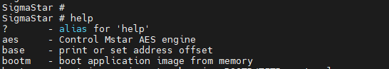
Now that we have the paws on the shell, let’s try to get some information that could be interesting about the device we are trying to break
SigmaStar # printenv
baudrate=115200
bootargs=console=ttyS0,115200 root=/dev/mtdblock2 rootfstype=squashfs ro init=/linuxrc LX_MEM=0x3fe0000 mma_heap=mma_heap_name0,miu=0,sz=0x1400000 mma_memblock_remove=1
bootcmd=sf probe 0;sf read 0x22000000 ${sf_kernel_start} ${sf_kernel_size};bootm 0x22000000
bootdelay=0
cpu_part_start=14950000
ethact=sstar_emac
ethaddr=00:30:1b:ba:02:db
fileaddr=23b82cf8
filesize=109
gatewayip=172.17.190.1
ipaddr=172.17.190.5
netmask=255.255.255.0
serverip=172.17.190.64
sf_kernel_size=200000
sf_kernel_start=50000
sf_part_size=6b0000
sf_part_start=950000
stderr=serial
stdin=serial
stdout=serial

Environment size: 643/4092 bytes
Here are the boot parameters passed to the kernel.
bootargs=console=ttyS0,115200 root=/dev/mtdblock2 rootfstype=squashfs ro init=/linuxrc LX_MEM=0x3fe0000 mma_heap=mma_heap_name0,miu=0,sz=0x1400000 mma_memblock_remove=1If we set the init parameter here to /bin/sh, we are telling the Linux kernel to run /bin/sh as init instead of system init. This gives us the root shell during the boot time.
SigmaStar # setenv bootargs console=ttyS0,115200 root=/dev/mtdblock2 rootfstype=squashfs ro init=/bin/sh LX_MEM=0x3fe0000 mma_heap=mma_heap_name0,miu=0,sz=0x1400000 mma_memblock_remove=1Then to boot on the shell, this is the command to use sf probe 0;sf read 0x22000000 ${sf_kernel_start} ${sf_kernel_size};bootm 0x22000000
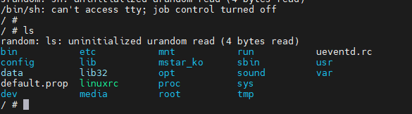
Sadly, this shell did not allow us to make changes to the system as the file system is read-only squashfs. If we had a writable filesystem, maybe we could add a script to run a telnet or ssh service on the system.

Obtaining the Firmware through U-Boot

There is a technique that use the very primitive memory display method that is offered by UBOOT.
It is possible to print the memory contents on the U-boot console using the md command. All that is needed is to know the starting address of the firmware in the memory and the size, than all this space can be printed on the screen.
The simplest way to find out this information is to look at the bootcmd parameter in the output of the printenv command.
SigmaStar # printenv
...
bootcmd=sf probe 0;sf read 0x22000000 ${sf_kernel_start} ${sf_kernel_size};bootm 0x22000000
...
The sf read command is used to copy flash content to RAM. 0x22000000 specifies from which address in RAM the content will be copied. This was the first value we needed.
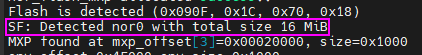
The other value we need is the flash size. We could already see this value when the bootloader first started. We have a 16 MB flash, which means 0x1000000 in hex.
Another way to find out the total mapped data size is to look at the partition information in the boot output.
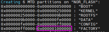
Get the data
Here is the command that will print all the content of the flash : md.b 0x22000000 0x1000000
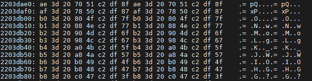
Here is an extract of what we can see in the terminal :

Process the data
I saved the output of the terminal in the file, that’s good, but now I have a file with the output of the entire console. Currently this file is still not a binary file, it just contains some plain-text and hex characters. It need to be cleaned of the unnecessary content in this file. Only memory output should remain. Something like this :
226404d0: 4d 40 26 68 b2 bf d9 97 4d 40 26 68 b2 bf d9 97    M@&h....M@&h....
226404e0: 4e 40 26 70 b1 bf d9 8f 4e 40 26 70 b1 bf d9 8f    N@&p....N@&p....
226404f0: 4f 40 26 78 b0 bf d9 87 4f 40 26 78 b0 bf d9 87    O@&x....O@&x....
22640500: 50 40 26 80 af bf d9 7f 50 40 26 80 af bf d9 7f    P@&.....P@&.....
22640510: 51 40 26 88 ae bf d9 77 51 40 26 88 ae bf d9 77    Q@&....wQ@&....w
22640520: 52 40 26 90 ad bf d9 6f 52 40 26 90 ad bf d9 6f    R@&....oR@&....o
22640530: 53 40 26 98 ac bf d9 67 53 40 26 98 ac bf d9 67    S@&....gS@&....g
22640540: 54 40 26 a0 ab bf d9 5f 54 40 26 a0 ab bf d9 5f    T@&...._T@&...._
22640550: 55 40 26 a8 aa bf d9 57 55 40 26 a8 aa bf d9 57    U@&....WU@&....W
22640560: 56 40 26 b0 a9 bf d9 4f 56 40 26 b0 a9 bf d9 4f    V@&....OV@&....O
22640570: 57 40 26 b8 a8 bf d9 47 57 40 26 b8 a8 bf d9 47    W@&....GW@&....G
Now this hexdump need to be converted into a binary file. The following python code should do the trick

import sys, struct

data_bin = bytearray()
with open(sys.argv[1]) as hexdump:
        for line in hexdump:
                data_hex= line[10:57].split(" ")
                for i in data_hex:
                        data_bin += struct.pack("B", int(i, 16))

binary_file = open(sys.argv[2], "wb")
binary_file.write(data_bin)
binary_file.close()
It is also available on GitHub, and if this specific one is not working, some other ones should be doing quite the same thing
 https://github.com/SungurLabs/Firmware-scripts/blob/main/hex2bin.py
Finally, this is a firmware of the device.
Examine the Firmware with binwalk
Now let’s extract it with the help of binwalk and examine it.
binwalk -e firmware.bin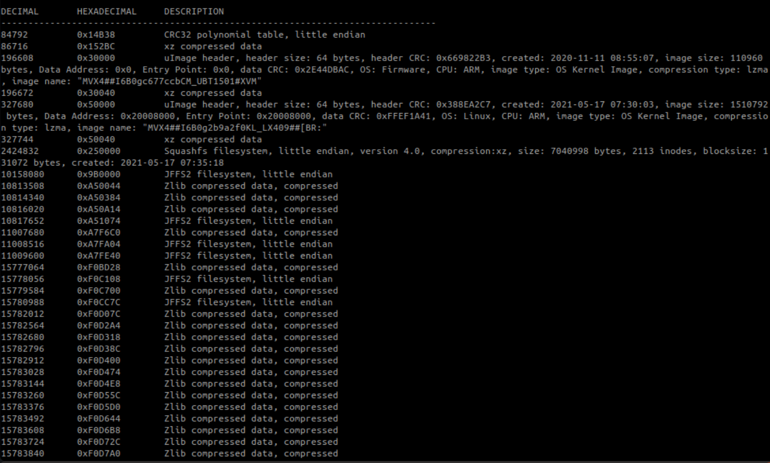
Time for backdooring the device
Now that we have the firmware, it might be interesting to try to add some elements in it to get access to the device once in “production” mode
Extracting the partitions
The first thing to do is to extract the partitions of the firmware and then access the file system that we want to modify. The following script can help to do so
import sys

partitions = [
	("boot", 0x0, 0x50000),
	("uImage_kernel", 0x50000, 0x200000),
	("squashfs", 0x250000, 0x760000),
	("data", 0x9B0000, 16777216-0x9B0000)
]

firmware = open(sys.argv[1], "rb")
for part, offset, size in partitions:
	firmware.seek(offset, 0) # Moves the cursor up to the offset.
	data = firmware.read(size)
	output = open(part, "wb")
	output.write(data)
	print("{} - saved!".format(part))
	output.close()
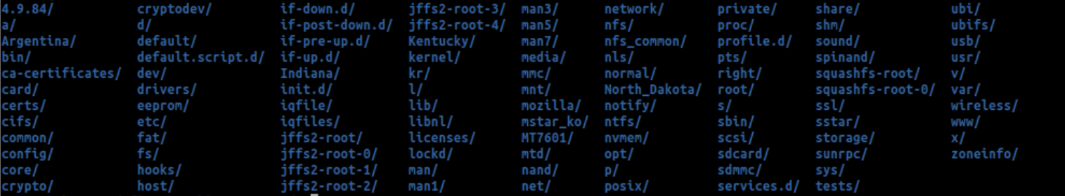
Decompress Squashfs files
However, after uncompressing this file system with the
unsquashfs tool, it is possible to make new additions to it. Then create a new squashfs filesystem with these updated files.$ unsquashfs -d squashfs_out squashfs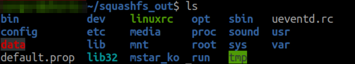
Time to build the door
One of the best places to add backdoor is init scripts(/etc/init.d/). Because these scripts are run while the device is booting and does not require a condition. The actual init script here is rcS, and it runs files in this directory that starting names begin with a capital S, in numerical order. These are the start scripts. Likewise, the rcK script is run at shutdown.
A good candidate to make a backdoor could be telnet. however, the device doesn’t have it’s binary. So we can add a statically compiled version of busy box containing it. Available at the following link
And then run it from the sdcard by editing the rcS script by adding this line
/mnt/sdcard/busybox-armv7l telnetdLet’s resquash all of our dirty modifications
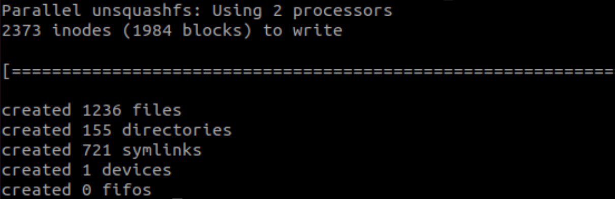
Adding backdoor is complete. Now it’s time to create a new squashfs filesystem with updated init script.
The tool used to do this is called mksquashfs. But first we need to know the compression type and block size of the squashfs to create. To get these informations, it is possible to look at the details of the original squashfs by running unsquashfs with the -s parameter.
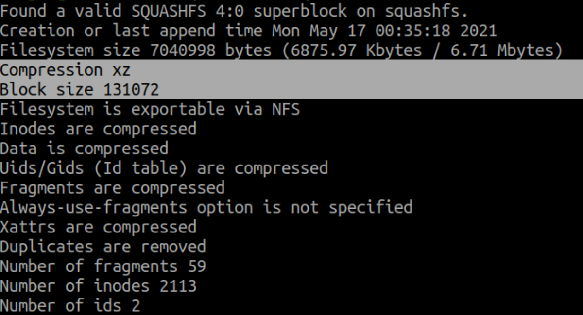

Compression is xz and blok size is 131072. Let’s create the new file system
mksquashfs squashfs_out/ squashfs_new -comp xz -b 131072
mv squashfs_new squashfs
Final repack
The last thing we need to do to create the final firmware is to repack the unpacked partitions. to do so, the following script should do the trick
import sys

partitions = [
	("boot", 0x0, 0x50000),
	("uImage_kernel", 0x50000, 0x200000),
	("squashfs", 0x250000, 0x760000),
	("data", 0x9B0000, 16777216-0x9B0000)
]

firmware = open(sys.argv[1], "wb")
for part, offset, size in partitions:
	p = open(part, "rb")
	data = p.read()
	firmware.write(data)
	if len(data) < size:
		size_padd = size - len(data)
		padd = size_padd * b'\x00'
		firmware.write(padd)
		# squashfs should be padded for alignment purposes
Pushing the new firmware to the device
There are two methods to upload the new firmware that has been modified to the device.
Using the SDCard AutoUpdate
One of them is firmware update process via sdcard.
The camera checking the existence of /mnt/sdcard/tf_update.img, /mnt/sdcard/tf_all.img, /mnt/sdcard/tf_all_recovery.img files in sdcard every time it boot up. We can start the update procedure of the device by placing the firmware on the sdcard (firmware has to be named tf_update.img).
However, this process is tricky because the device does the signature verification of the file.
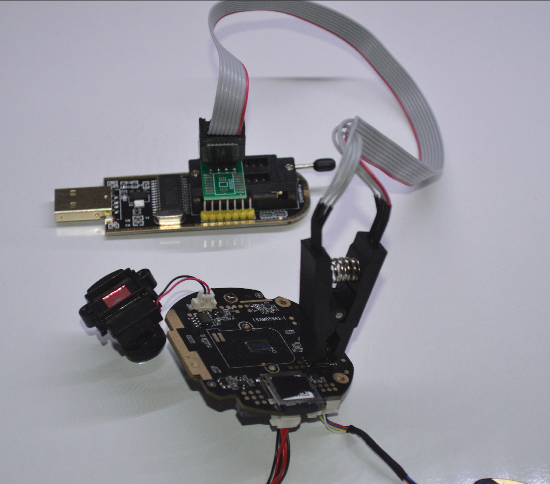
Direct access flash
The other method is firmware uploading via direct access to flash. For this,let’s use a CH341A flash programmer with SOIC8 clip.
We’ll use the flashrom tool to write the firmware to flash. The -p parameter is used for the programmer name, and the -c parameter is for the flash chip name.
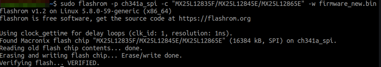
After about 10 minutes of operation, The device have now written our backdoored firmware to flash. Now it’s time to power up the device and test if the telnet port is active.
Testing the backdoor
after some shenanigan I managed to get the IP of my brocken device. Once scanned with nmap, we can see that there is an open port on 23
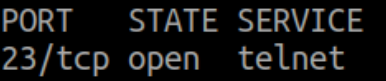
If we try to access it over telnet, here is the result