AP3400 MOSFET - Discovery
Introduction

One of the things I want to be able to achieve is fault injection. To do so I need to be able to perform power cuts at precise moments. The best way I found in documentation achieve this goal is by using MOSFETs that are electrical components that act like switches.
So I got my hand on several of these tiny components and made some tests to understand how it is working.
The process
Step 1 : Solder the MOSFET to a board
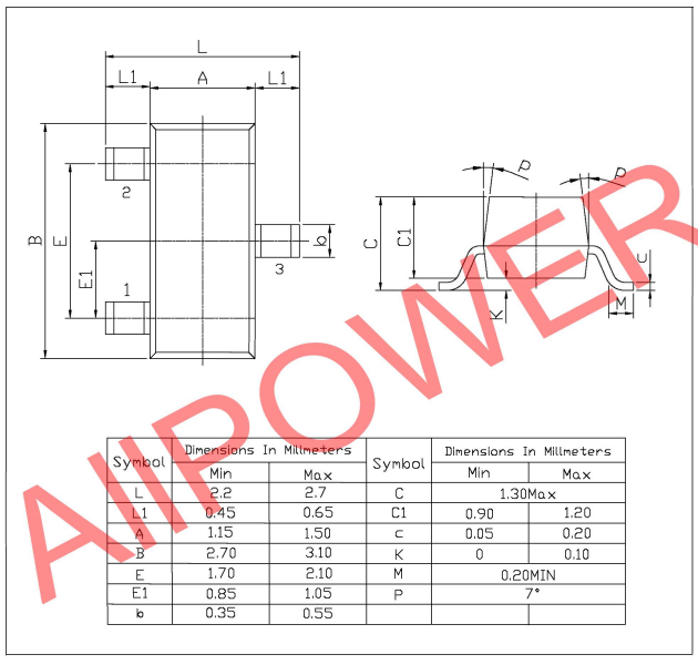
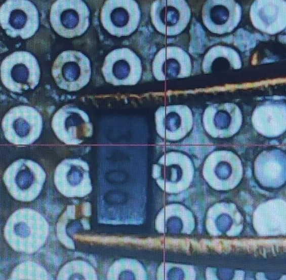
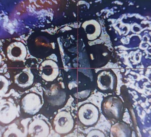
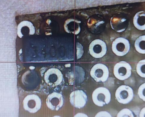
MOSFETs are really tiny components when dealing with low Amps and Volts as you can see in the specs and on the following photos
I decided to solder it to a small board so it would be easier to then connect it on testing installation. Originally tried using some soldering paste, it went quite bad as once liquified the solder would get in the small holes of the board.
It then decided to apply some flux and used regular solder to get the chip into place on the board
Now that the chip is soldered to the board, it’s time to test it’s connectivity to make sure the solder was properly made (which I doubted at this time)
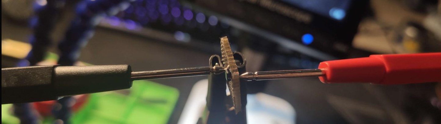
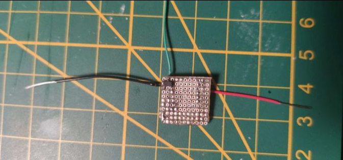
Step 2 : Wire the chip
It got to work first try, perfect. now that we have the chip on a board I decided to add some wires to each pins for further operations

Step 3 : Let’s test
Now that I have a chip that I can easily use for testing, I decided to go with a basic LED blinking setup as follow :
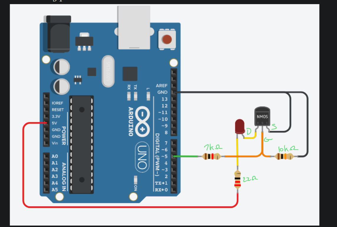
The Arduino UNO would be loaded with the following script that makes the LED turn HIGH or LOW every 1 second
void setup(){
  pinMode(5, OUTPUT);
}

void loop(){
  digitalWrite(5, HIGH);
  delay(1000);
  digitalWrite(5, LOW);
  delay(1000);
}

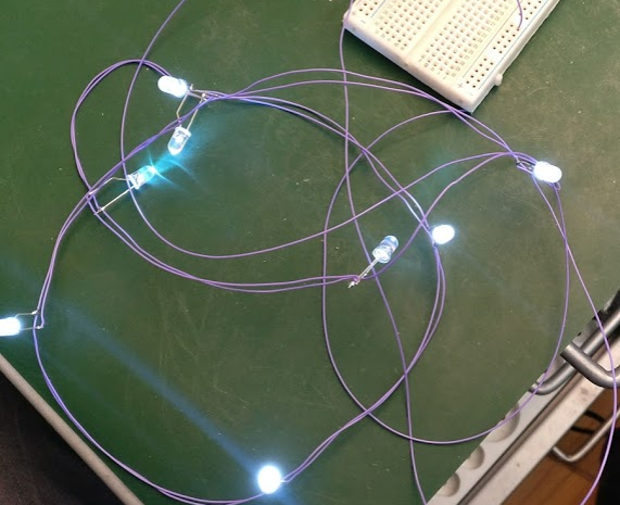
Here is a pic of the real setup (quite messy, not super stable)
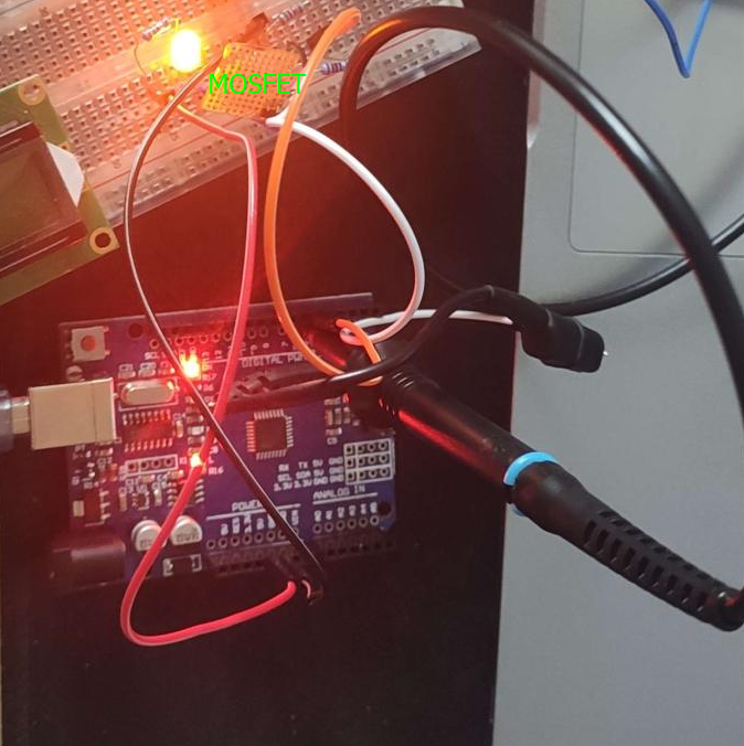

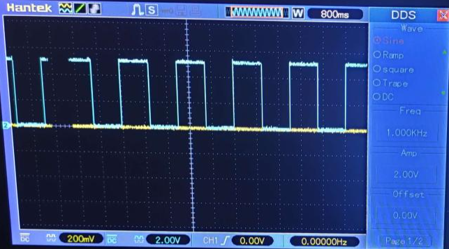
It can be seen on the photo that there is an oscilloscope probe on the circuit. I installed it for debug as the LED initially wasn’t blinking. I wanted to make sur the signal was pushed from the Arduino UNO using my DSO
After a bit of tweacking, I found that one of the resistors where not properly held on the breadboard so I changed the position and everything now works fine
Sources